Simio and Simulation: Modeling, Analysis, Applications - 7th Edition
Chapter 8 Animation and Entity Movement
The goal of this chapter is to expand our knowledge of animation and entity movement by adding more context and additional concepts to what you’ve seen in earlier chapters. We’ll start by exploring the value of 2D and 3D animation to a typical project. Then we’ll discuss some additional animation tools that are at our disposal. At that point we’ll “move” on to discuss the various types of entity movement, providing a brief introduction to free space (off-network) movement, and a somewhat more detailed exploration into the Standard Library objects that support entity movement.
8.1 Animation
In Section 4.8 we introduced some basic animation concepts so that we could animate our early models. In this section we’ll revisit and expand on those topics. We’ll start by discussing animation, why it’s important, and how much is enough. Later in this section we’ll introduce some additional tools and techniques available to produce the animations you need.
8.1.1 Why Animate?
Every model we’ve built so far includes some amount of animation. While a few commercial simulation products still exist that are text-based with no animation, in general at least some level of animation has been included in most simulation products for decades. There is a reason for this — animation makes it much easier to build and understand models.
8.1.1.1 Understanding the System
Simulation models are often large and complex. From a modeler’s perspective, it’s hard to manage this complexity and understand both the detail and the “big picture” of the project. Visualizing with even a simple animation aids understanding. Ideally the simulation software you’re using will make simple animation very easy to do. Most modern products do just that, and in fact the default 2D animation provided in Simio goes well beyond the minimum requirements and takes little or no extra effort on the part of the modeler.
While there are many components to effective model verification, careful review of an animation is usually a key. You can study the details by watching model progression step by step. You can quickly analyze common or unusual situations by studying model reaction around those events. And you can often discover problems and opportunities just by studying an animation in fast-forward mode, stopping from time to time to study the details.
Caution: While animation is important in verification it should never be the only, or even primary, mechanism for verification. Effective verification requires the use of many different techniques.
8.1.1.2 Communication
Two common high-level simulation goals are to understand the system and to provide benefit to stakeholders. Animation helps with both. If you provide a page of numbers or a diagram of model logic to a stakeholder, the typical response will involve eyes glazing over, often quickly followed by entry into a near-catatonic state. But show them an animation that looks familiar and they’ll instantly perk up. They’ll immediately start comparing the components, movements, and situations in the animation to their own knowledge of the facility. They may start discussing design aspects amongst themselves just as though they were looking through a window at the real system. At this point, you’re well along the way to having delivered on both high-level objectives. At the top end, animation quality may be good enough for the stakeholders to use it for outside communication — not only promoting the project, but often even using it to promote the organization.
Of course getting to this point is rarely free. Depending on the modeling software you use, building an animation suitable for use with stakeholders may be quite involved, especially with products for which animation is built independent of the modeling. Sometimes animations are created in a totally separate animation product. And sometimes the animation can only be run in a post-process mode after the model run has completed. Such a post-process analysis severely limits the level of model experimentation possible.
Fortunately, the animation that Simio creates by default is often fairly close to “stakeholder ready.” Simio’s animation is built-in, in fact created automatically as you build the model. And it runs concurrently so you have full interactive capabilities while watching the animation.
8.1.1.3 The Importance of 3D
So far in this discussion we’ve not even mentioned 3D animation. You might be wondering if it’s necessary or why anyone would use it. Fifteen years ago we might have told you that 3D animation was unnecessary in most projects and not worth the effort. But a great deal has changed in that time. First, high-quality graphics have become routine and even expected in our daily lives. Most people now easily relate to 3D animation and can immediately appreciate its use. Because of this new frame of reference, 2D animations tend to look primitive and don’t engage the stakeholder or inspire their understanding and confidence to the same degree as 3D. Second, the effort involved in creating 3D animations has decreased tremendously. A modeler no longer requires extensive drawing skills or access to a large custom symbol library. And they no longer need skills in a complex drawing package. Modern software allows a modeler with minimal artistic skills to generate compelling animations without any special skills, tools, or custom libraries.
Animation is often important and many people find it enjoyable and rewarding to work on. But you can have too much of a good thing. It’s easy to get so involved in making your animation look “just right” that you spend inadequate time on model-building, validation, analysis and other important parts of the project. Keep in mind that, just as in the rest of your modeling, the animation is an approximation of the real system. We’re trying to develop animation that’s sufficient to meet the project objective, and no more. Determine with your stakeholders the appropriate level of animation required and then stick to that plan. Save animation “play time” for after all other important aspects of the project have been completed.
8.1.2 Navigation and Viewing Options
If you’ve not yet disabled it, you may still be seeing a gray area at the top of your Facility Window. If you’ve already disabled it or want to bring it back as a reminder, recall that pressing H while in the Facility window will toggle it on and off. Let’s explore these navigation controls in a bit more detail.
- To toggle between 2D and 3D you can press the
2and3keys respectively, or you can click on the2Dand3Dbuttons in the View Ribbon (refer to Figure 8.1). - You can pan (move) the facility window contents by left clicking in an empty space and dragging the window. Caution: If you happen to click on an object (for example a large background object) you’ll move the object instead of pan the view. To avoid this you can either click and drag using the middle mouse button , (which will not select an object) or you can right click on the background object and enable the Lock Edits option to prevent that object from moving.
- If you have a mouse with a scroll wheel (highly recommended) you can zoom the view in and out by scrolling the mouse wheel. If you don’t, then you can accomplish the same action with a Control-Right Click and move the mouse up and down.
- You can resize or rotate an object using its handles, the green dots that appear when you select an item. If you click and drag one of the handles, it will resize the object. If you Control-Left Click on a handle you can rotate the object.
- Clicking the
View Allbutton on the View ribbon will resize the Facility window so that your entire model is in view. This is particularly useful to return to a familiar view if you’ve been zooming and panning and “lost” your model objects. - The Background Color button on the View ribbon changes the background color of both 2D and 3D views. Although some older models may have a black background in the 3D view, it is no longer possible to create different background colors for 2D and 3D.
- The
SkyboxandDay/Night Cyclebuttons control how the background above your animation looks and changes. This is particularly useful for outdoor models like ports and transportation networks.

Figure 8.1: Simio View ribbon.
There are a few actions applicable only when you’re in the 3D view:
- Right-click and drag left and right to rotate the view in 3D.
- Right-click and drag up and down to zoom in and out.
- Hold down the
Shiftkey while moving an object and you’ll move it up and down in relation to the floor. - Hold down the
Controlkey while moving an object and you can stack it on top of other objects rather than overlapping it. - Pressing the
Rkey in the 3D view or clicking theAuto Rotatebutton on the View ribbon will start the 3D view rotating. PressingEscapewill stop the rotation.
The Visibility ribbon illustrated in Figure 8.2 helps you fine tune the look of the animation:
- The Visibility group contains buttons that toggle on and off specific display components. In many cases you may want to disable display of most or all of those items to make your animation look more realistic. Note that you may have to enable some of those buttons later if you want to interact with the model. For example, you cannot select a node if Nodes animation is disabled.
- The
Direct ShadowsandDiffuse Shadowsbuttons in the Visibility group provide finer control over how shadows appear around your objects. - The buttons in the Networks grouping provide a flexible way to see individual or sets of networks of your travel paths.
- The Layers subsection allows for objects, animations, and graphics to be placed on different defined layers in the model.
Refer to the Simio Help for more information on the use of these features.
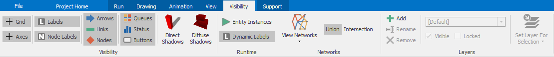
Figure 8.2: Visibility ribbon.
When you have your model ready to show, there are a few more helpful features on the View ribbon:
- A View is a particular way of looking at your model including 2D or 3D, its zoom factor and rotation. The Named Views grouping allows you to add views with the
Add Viewbutton — this allows you to provide a name for the view you currently have on your screen. Manage Views allows you to edit or remove an existing view. The Change View button is a two-part button. The top part cycles you through sequentially all named views. The bottom section provides a list so you can select which view to display. - The Camera Tracking group contains items to determine the vantage point of the camera as well as the ability to focus the camera on a particular object or even have the camera ride just in front of or behind a moving object like an entity or vehicle.
- The Camera Sequences group allows you to define the timing and sequence of multiple camera moves that can help prepare a presentation to “tell a story”.
- And finally the Video group allows you to record video (avi) files of your animation and related activities.
In addition to the options on the View and Visibility ribbons, there is one more viewing option of interest that is located over on the Project Home ribbon. The Render to Oculus button will enable or disable rendering the active 3D view to an attached Oculus HMD device. While this technology is still somewhat new and expensive, the animation can produce compelling effects, letting you walk through a model almost like being there.
8.1.3 Background Animation With the Drawing Ribbon
Let’s talk next about the things that appear in your model but don’t move, or static animation. While Simio doesn’t intend to be a drawing tool (there are very powerful tools like Google Sketchup available for free), it does provide basic drawing and labeling tools as well as the ability to import symbols and the capability to change how those drawn and imported symbols look. Taking advantage of these tools can be a quick and easy way to improve the realism and credibility of your model. Let’s look at the components on the Facility window Drawing Ribbon illustrated in Figure 8.3.
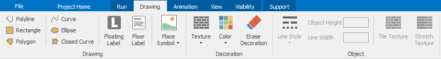
Figure 8.3: Facility window Drawing ribbon.
The Drawing Group on the left side of Figure 8.3 starts with six drawing tools to create some basic objects: Polyline, Rectangle, Polygon, Curve, Ellipse, and Closed Curve. If you’re unfamiliar with any of these shapes, we suggest that you experiment with them to see how they work. When you’re drawing most shapes, after you click the last point, right-click to end. Hitting the Escape key will abort the attempt and erase your drawn points. You may notice that many of them appear to have an extra point. That’s the rotation point. You may move that rotation point to any position. If you Ctrl-click and drag any of the other points, the entire object will rotate around that rotation point.
If you skip over to the Decoration and Object groups in the drawing ribbon, you’ll see tools to change the looks of these basic objects including the color, texture (pattern), options to tile or stretch that texture, line style and width, and object height. We’ll leave it to you to explore the full capabilities of these tools, but here are a few applications and tricks that might stimulate your imagination:
- Making a wall: Add a line the length of the wall. Set the Line Width to perhaps
0.1meter. Set the Object Height to perhaps2meters. Go to 3D view. Click on theTexturebutton and select a texture (perhaps a brick pattern), then click on the wall object to apply the texture. - Creating a company logo: Find a
.jpgfile with the logo you want. Save that file in your Public Documents (the exact name of this varies depending on your operating system) ..Simio..Skinsfolder. This will then automatically appear as a choice under theTexturesbutton. Draw a rectangle similar in shape to the logo. Apply your logo texture to the top of your rectangle. Another approach is to make your rectangle tall and skinny, then apply the logo or any texture to the flat side and it will appear like a sign, billboard or TV monitor. - Creating a simple building: Create a rectangle. Give it height. Apply a texture to the sides. Extra credit — take a photo of the face of your favorite building and apply it to your building. (Of course you can get much better buildings, perhaps even your own, from Trimble 3D Warehouse or Google Maps.)
Speaking of maps, if you look on the View ribbon, you will see that Simio also supports Graphic Information System (GIS) maps. You must first select the map view and set the map location by address or lattitude/longitude. An interactive background will then fill your screen. Not only can you draw on this, but you can place nodes on this, highlight any two nodes, and have the GIS system connect the nodes using the displayed road system. This system requires an active internet connection, so if you subsequently load the model without an internet connection, your background will be blank.
To finish our discussion of the Drawing ribbon, there are three buttons we’ve skipped. Floating Label creates a simple label that “floats” in the air and will always face you no matter your viewing direction. It also always displays at the same size regardless of zoom level. A Floor Label, as the name might imply, appears as though it has been painted on the floor. It can have multiple lines and you can choose color, size, and formatting options. Don’t miss the fact that you can embed expressions inside the text so you can create dynamic and informative labels.
We saved the best button for last. Place Symbol provides many different options to place a symbol as part of your model background. The top part of the button provides easy access to place another of the last symbol you selected (if any). The bottom part of the Place Symbol button brings up a large dialog that provides three main choices:
- You can scroll around in the built-in Simio symbol library to select a symbol to place, similarly to what we did in Section 4.8.
- You can Import Symbol from a local file already available to you. Perhaps this is a file you’ve created using Sketchup, or maybe a DXF file exported from some CAD program. Or you can import an image file like a JPG, BMP, or PNG file. A caution here is that DXF files can be quite large. They are often created at a detail inappropriate for simulation (e.g., they contain things like the threads on the nuts and bolts that hold the building structure together). If you plan to use a DXF file, it’s best to delete the unnecessary detail before you export to the DXF file. Tip: Often, a 2D building layout as found in a JPG or even
.pdffile is a good basis for an animation. It’s a very efficient way to provide scale and background and then you can add 3D objects (possibly including walls) to provide the depth. - You can Download Symbol from Google 3D Warehouse as we also discussed in Section 4.8. Tip: When possible, search for low poly symbols. This refers to symbols with a low polygon count (a measure of display complexity). Even some Google 3D Warehouse symbols have the same problem as DXF files — their complexity and detail is inappropriate for simulation animation. So you might select a very nice picture of the “perfect” fork lift truck only to find that it inflates your model size by 10 MB because it’s detailed down to the bolts that hold the muffler bracket in place. In some cases you can load such a symbol into Sketchup and remove the unnecessary detail.
8.1.4 Status Animation With the Animation Ribbon
In addition to seeing objects moving on your screen, often you want other types of visual feedback and interaction to help assess model performance. Not only does Simio provide a set of tools for this, it also provides a choice on how to display them: in the Console window or in the Facility window.
8.1.4.1 Console window
Every model has a Console window designed as a place to display selected graphical status indicators and interactive buttons. The Console window for any model is defined using the Console window under the Definitions tab. There you’ll see something that looks similar to the Facility window, except that you can’t place library objects here; only the items described in this section can be placed in a Console window. There are two advantages to putting status items in the Console window:
- It allows you to keep business graphics separate from your facility animation. You can then hide the business graphics or dedicate a certain portion of your screen to viewing them.
- If your model is later used as an object, this console is available from that object’s right click menu. The user of your object will see the status display that you designed. The console from an embedded object has the additional advantage that it can be displayed outside of the Simio window space, even on a second monitor if one is available. TIP: The console can be a great place to store documentation of your object. Just add your documentation in a floor label.
8.1.4.2 Facility Window
You can also place your status animations in the Facility window. The advantage of placing them here is that they can be arranged adjacent to the objects of interest, or you can place them elsewhere in your model and associate one or more named views with them. The main disadvantage is that these are primarily 2D business graphics and they don’t always look good in the 3D Facility window.
8.1.4.3 Status Animation Tools
Regardless of the window you choose to display your status objects, you have a similar set from which to select, but it’s quite different from the Facility window Drawing ribbon we discussed in Section 8.1.3. If you want to add status objects to your Facility or Console window you’ll have to click on the Animation ribbon (Figure 8.4).
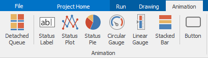
Figure 8.4: Facility window Animation ribbon.
The tool set in the Animation ribbons contain:
- Time Plot: Displays one or more values as they change over time.
- Pie Chart: Compares two or more values as a proportion of the total.
- Bar Chart: Displays the value of an expression over time.
- Circular Gauge and Linear Gauge: Provide a more visually compelling display of a model value.
- Status Label: Displays static text or the value of any expression.
- Status Table: Displays the vales of expressions defined in a separate source table.
- Floor Label: Similar to the Floor Label we discussed in Section 8.1.3
- Queue: Adds animation to show entities that are waiting in a queue.
- Stack: Adds a status stacked bar for displaying container contents.
- Button: Provides a way for a user to interact with the model. Each time the button is clicked an Event is triggered, which could be linked to a process.
8.1.5 Editing Symbols with the Symbols Ribbon
When you click on most objects in the Facility window, the active ribbon automatically changes to the Symbols ribbon (Figure 8.5). This ribbon allows you to customize the animation of that object by modifying the symbol(s) and adding animation features. Although at first glance it looks like a lot of new options, if you take a second look, you’ll discover many familiar features. In fact, way back in Section 4.8 we used the Project Symbols category of this ribbon to select a new ATM Customer. And the Import Symbol and Go To 3D Warehouse ribbon buttons are similar to options on the Place Symbol button we discussed on the Drawing ribbon. Likewise, the items in the Decoration group are identical to those in the Drawing ribbon Decoration group.
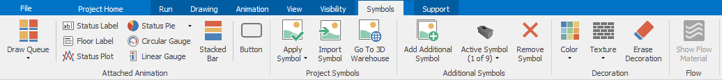
Figure 8.5: Symbols ribbon for symbol editing.
8.1.5.1 Attached Animation
The Attached Animation group looks very similar to the Animation ribbon in Figure 8.4 but there is one very important difference summed up by the word “Attached.” Since you got here by selecting an object, if you place any items from the Attached Animation group, those items will be attached to that selected object. In the case of fixed objects like a Server, this just means that if you later move the object on the screen, the attached items will move along with the object. But an interesting situation occurs when you attach an item to a dynamic object like an Entity, Vehicle or Worker. In this case the attached items will travel with each dynamic object as it travels through the model. Let’s examine a few interesting applications of this:
- The green horizontal line across the default Vehicle symbol is an attached queue that animates
RideStation.Contentsto show the entities that are being carried by (i.e., riding on) the vehicle. - In a similar fashion, if you’re grouping your entities by using the Combiner object, you can display the group members by adding an attached queue to your parent entity object. If you animate the
BatchMembersqueue you’ll see the members currently in the batch of the parent. You can find examples of this in SimBitsCombineThenSeparateandRegeneratingCombiner. - You can also display text or numeric information with an entity. In SimBit
OverflowWIP, we wanted to be able to verify the creation time of each entity, so we added an attached status label using the expressionTimeCreatedon the entity. We also rotated the label so we could still read it when it’s in a queue.
Adding attached information can be both visually compelling and valuable for verifying your model. Since attached animation becomes part of (or even “inside”) the object, the scope for attached animation is the object itself. The advantage of this is that you can reference any expression from the perspective of the object. So in the first bullet above, for example, we referenced RideStation.Contents, not Vehicle1.RideStation.Contents. The latter wouldn’t work because it would be at the scope of the containing model, rather than the object itself.
8.1.5.2 Additional Symbols
The last item group on the Symbols ribbon is the Additional Symbols group. These features allow you to add, edit, and remove symbols from a set of symbols associated with an object. By default each object has only one symbol, but in many cases you’d like to have a set of symbols for that object. Some useful examples include:
- A entity that’s a single entity type, but you want to illustrate some variety (such as a Person entity, but you want to show 5 or 10 different person symbols).
- An entity that changes as it progresses through the model (e.g., a part that changes its picture as it gets processed or when it fails an inspection.
- A Server (or any object) where you want to show different pictures for each state it may enter (e.g., Busy, Idle, OffShift).
In the Properties window of most objects you’ll find a category named Animation (Figure 8.6)
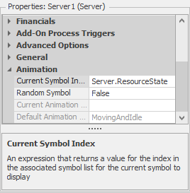
Figure 8.6: Default animation properties for a server.
that contains properties Current Symbol Index and Random Symbol. Note that these properties are disabled unless you’ve added at least one additional symbol to your object. Using these properties allows you to select from between the specified symbols.
The Random Symbol property is looked at when an object is first created. If this is set to True, then it will automatically select one symbol from the set of defined symbols. For example, in case 1 above, if you had defined 3 person symbols: a man, a woman, and a child, then setting Random Symbol to True would result in each entity having a 1/3 chance of using each symbol.
The Current Symbol Index property is used to tell Simio where to look to determine that object’s symbol number. Symbols are numbered starting at 0, so if you have 5 symbols they’ll be numbered 0 through 4. To animate case two above, set Current Symbol Index to ModelEntity.Picture and then assign that entity state to the index of the picture you want to display as the entity progresses through the model.
The Current Symbol Index property doesn’t have to be an object state — it can be any expression. For example in SimBit OverflowWIP, we wanted an obvious visual cue to show in which hour a part was created, so we used the Current Symbol Index expression of Math.Floor(ModelEntity.TimeCreated) on the entity. Since time is in hours, it uses a new symbol for each hour of the day.
The default Current Symbol Index property for a Server is _ServerName_.ResourceState. This assumes nine symbols that are supplied with the library, one for each of the standard resource states 0 through 8 for Starved, Processing, Blocked, Failed, OffShift, FailedProcessing, OffShiftProcessing, Setup, and OffShiftSetup respectively. Tip: View the “List States” topic in help to see the state definitions for other objects.
8.1.6 More Realistic Entity Animation
In section 4.8 we discussed Simio’s symbols library and we briefly discussed the folders containing animated people. Recall that the filters (Domain, Type, and Action) illustrated in the bottom of Figure 4.34 allow you to more quickly find the best symbol. Specifically the Action filter has two choices: Animated and Static. In this context, “Animated” refers to a symbol that has movement internal to the symbol itself. Simio provides the capability for more advanced users to do this with any type of symbol (for example a machine throwing sparks, or a vehicle with turning wheels). The included symbol library only provides this for animated people. But this can be used to produce compelling animations (Figure 8.7).
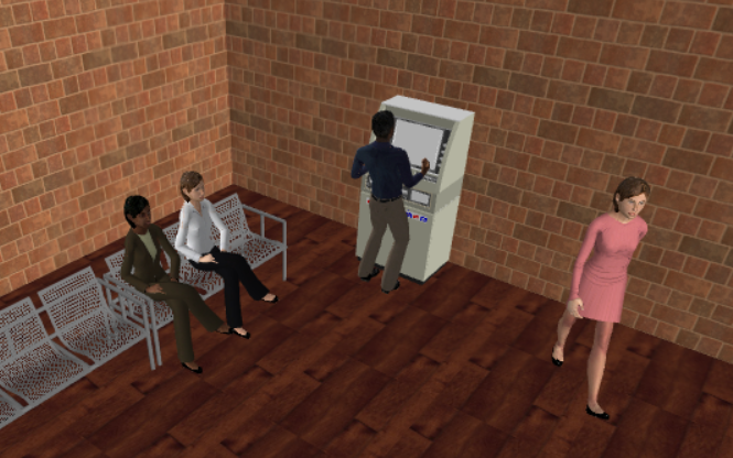
Figure 8.7: Animated people in a ATM facility.
A wide variety of people and clothing styles/colors are included. For example you can choose from men, women, girls, boys, elderly, and even cartoon characters. They are available dressed in business attire, health care attire, coveralls, and informal wear. And many race/ethnic backgrounds are included as well. The primary benefit of using these symbols is their ability to “move” more realisticly. The most obvious is people who walk (e.g., their legs and bodies move naturally as they move). Figure 8.8 illustrates the 22 predefined movements available with the standard Simio people. Tip: This menu can be found under List Animations of Active Symbol only when an active symbol has been applied (e.g., applying an “animated” symbol to an entity).
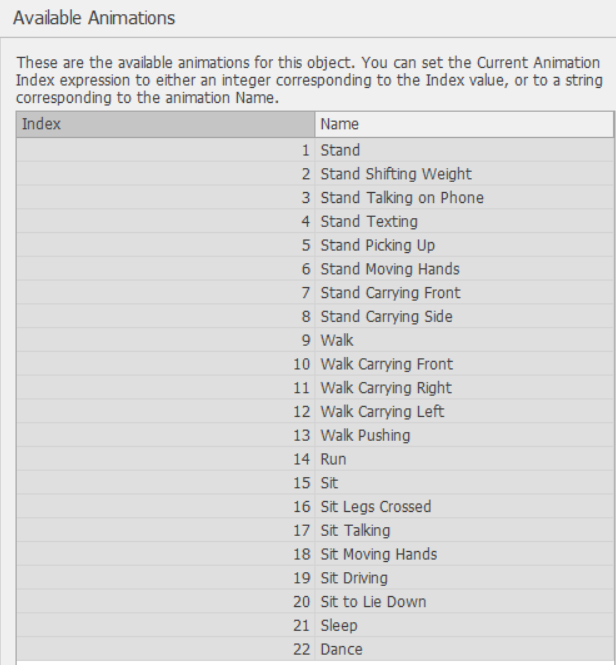
Figure 8.8: Available animated people actions.
As you might observe from the list, there is pretty good flexibility. For example if you wanted to animate a person pushing a lawnmower or wheelchair, you might choose action 13 - "Walk Pushing". Or if you wanted to animate a person on a hospital bed, you might choose action 21 - "Sleep". Many of these actions are built-in behavior when an animated person symbol is selected. For example, when an animated person is waiting in a queue, it will randomly cycle between the various standing actions (1-8) to provide some reality.
One way to control the automatic behavior is to adjust the properties illustrated in Figure 8.9. To specify a specific action, assign ModelEntity.Animation to the action. For example, assign ModelEntity.Animation to "Sit" just before entering a queue to have them sit while waiting. Then after leaving the queue assign ModelEntity.Animation to “” to restore the default.
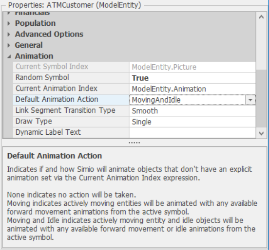
Figure 8.9: Animation properties of an entity.
8.1.7 Model 8-1: Animating the PCB Assembly
Let’s use some of this new-found knowledge to continue work on our PCB model. But before we start, recall our earlier admonition to develop animation that’s sufficient to meet the project objective, and no more. Sometimes you may not be able to find exactly the right symbol or display things in exactly the precise way, but that’s okay — a reasonable approximation is often good enough. You can always improve the animation later as time and objectives dictate.
Let’s start by loading our PCB Model 5-3 discussed in Section 5.4 and save it as Model 8-1. Since this is a fictional system, we can take some liberties in animating it. First let’s find a better symbol to use for our PCB object.
- Click on the
PCBobject and then click on theSymbolslibrary. Search the library to see if there’s a symbol there that could be used as a PCB (recall that this is a small board with computer chips on it). Unfortunately nothing appears to be close, so let’s keep looking. - Again click on the
PCBobject and then click on theDownload Symbolbutton. If you’re on-line, this will bring up the Trimble 3D Warehouse search screen. Do a search onPCB. In our search we found over 1400 symbols involving that term (most having nothing to do with our topic) but there were several good candidates. Select the symbol namedGumstix Basix R1161and then selectDownload Model. TIP: You might think that other symbols likeNat's PCBis an appropriate symbol, and it could be. But after you download it you would find that your model size has increased by several megabytes. This is because that symbol has a very high polygon count - a measure of the complexity of the symbol. If you happen to download such a large symbol and you do not want it bloating your model, you can replace the symbol with a smaller one and then delete the large symbol from theProject\(\rightarrow\)Symbolswindow (click on the folder icon in the Navigation window then click on Symbols View from the left panel). Make sure that you are not using the symbol in the model before deleting it, though. Otherwise, the symbol instance will still remain in the model. - After the symbol downloads it will be displayed in the Simio Import window. Here you have a chance to rotate, resize, and document the symbol. Let’s do all those. Use the
Rotatebutton to rotate it so the short edge is to the right. We want the longest dimension to be 0.3 meters, so change the Width to be0.3(you’ll note that the other dimensions change proportionally). And finally we’ll change the Name toPCBand the Description toGumstix Basix. - The symbol will appear quite small, but no worries — we’ll deal with that later.
Let’s follow a similar process to change our chip-placement machine.
- Since there are no placement machines in the Simio symbol library, we’ll skip that step. Click on the
Placementobject and then click on theDownload Symbolbutton to bring up the Trimble 3D Warehouse search screen. Do a search onplacement machine. - We selected the
Fuji QP351and downloaded it. It downloaded in the correct orientation and size, so we can just clickOKto accept it as is and apply it to thePlacementobject.
The three parallel stations are also placement machines, so we could simply use the same symbol for them. But they actually represent higher-tech machines that do more accurate placement, so let’s pick a different symbol for those machines. Repeat the above process starting on the upper machine. Select a different machine (we chose the Fuji QP 242e because it looks high-tech) and download it. Adjust the rotation and size of your selection appropriately — we had to rotate ours 180 degrees and change the width to 1.5 meters.
You may have noticed that each time you download a symbol, it gets added to your project library. So now you can click on each of the other two parallel machines and apply the same placement symbol you just downloaded. Both the inspection and the rework are manual operations, so we’ll animate both of them using a suitable table symbol. You can download another symbol if you like, but we think the TableSaw in the symbol library under the Equipment category looks close enough to a work table to meet our needs, so we just applied that to both manual stations.
If you’ve followed along as instructed, you may be feeling unhappy now. Our symbols don’t look very nice at all against the white background and in fact they look pretty small. The problem is one of model detail. In our earlier models we were not concerned about the details of part and machine sizes and their proximity because we were making the simplifying assumption of instantaneous movement between stations. While this is often a very good assumption at the beginning of a modeling project, you’ll usually come to a point where it does matter — that’s where we are now.
In many cases you’ll have a JPG or other image file of the system layout that you could use as a background image. That can then be used for sizing and placing your equipment appropriately. In this case we don’t have that. As we were selecting symbols, we’ve been providing some selected dimensions. But in our original model we placed the machines arbitrarily about 10 meters apart and in the real system they are only about 1-2 meters apart. Before we start moving machines around, let’s clean up the associated objects for each of our servers:
- Zoom into the three parallel stations so they fill the screen.
- Start at the bottom of the screen (the easiest to see) and click on the input node (the one named
Input@FinepitchSlowStation) and drag it so that it’s adjacent to the input side of the placement machine symbol. Repeat that with the output node. It may look good in the 3D view, but we often flip back and forth between 2D and 3D to fine tune the adjustments to look good in both views. The nodes and paths in your animation should now look similar to those in Figure 8.10. - The queue named
Processing.Contents(the green line above the machine in the 2D view) shows what’s currently processing on the machine. It would look better if this were on (or actually inside) the machine. In the 2D view, drag the queue so it looks like it’s in the bed of the placement machine. At this point, it’s still on the floor. Move to the 3D view and use the Shift-Drag to lift the queue up so it’s visible above the bed. Then move both ends of the line so the queue is centered on the bed as illustrated in Figure 8.10. Tip: It’s easy to “lose” a small symbol inside of a large one, so it’s generally best to leave the queue longer than the object on which you’re displaying it until you’re sure it’s in the right place. Only then should you adjust the length. - Shorten the length of the Output Buffer queue and move it adjacent to the output side. Since we’re using a zero capacity input buffer, the queue on the input side will never be used — delete it to avoid confusion.
- Now repeat that whole process (the above three steps) with the other two placement machines.
- Follow the same process for Placement, Inspection, and Rework except that you should not delete their input-buffer-queue animations because they may still be in use.
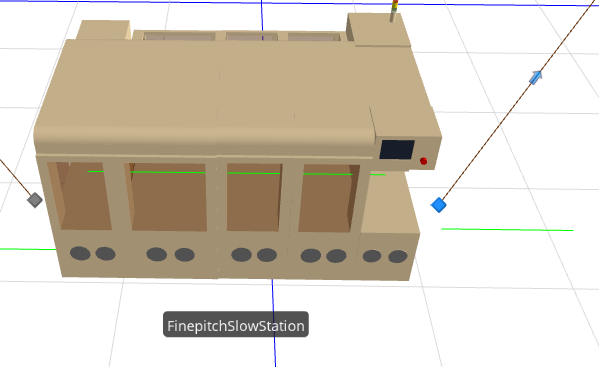
Figure 8.10: Editing animation on FinepitchSlowStation.
After completing all of the above, your model still looks odd. If you run it now, the PCB symbols that are moving around will look like little dots. We’ve fixed the scale of the symbols and their associated objects, but we’ve not yet adjusted the scale of the layout to reality. Let’s take care of that now:
- In the 2D view, select
FinepitchSlowStationand drag it upwards so it’s parallel to and about 1 meter away from FinepitchMediumStation. (You can take advantage of the grid lines to help.) Then selectFinepitchFastStationand drag it downwards so it’s parallel to and about 2 meters away from FinepitchMediumStation. Note that your queues and nodes will move along with each object. Consider why that is. - Move the rest of the objects so that there is approximately 2 meters of horizontal distance between the objects.
- The objects that are still using the standard library symbols now appear quite large. You may replace them with other symbols if you wish. We just dragged a corner of the symbol to reduce the sizes an appropriate amount.
As a last quick enhancement, let’s add a floor and some walls:
- In the 2D Facility view, use the
Rectanglebutton on the Drawing ribbon to draw a rectangle that completely covers the floor area of the equipment. Use theColorbutton to make it gray. If you’d like the floor grid to show through, go to the 3D view and use Shift-drag to move the floor slightly down. Now right-click on the floor and enableLock Editsto prevent accidentally moving it. - Back in the 2D view, draw a polyline around the left, back, and right edges of the floor. Still in the Drawing panel, give the wall a Width of
0.2and a Height of1meter (so we can still easily see over it). In the 3D view, select an interesting texture from the Texture button and apply it to the wall. Again, right click toLock Editsand prevent accidental movement of the wall.
In this section we’ve used some of the simple techniques we learned in earlier sections to improve our animation a bit and make it roughly to scale (Figure 8.11).
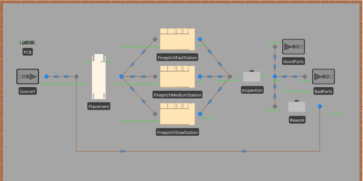
Figure 8.11: 2D Animation of PCB to scale.
Sometimes it’s convenient to do this “after the fact” as we just did, but generally it’s easiest to build the model at least roughly to scale from the start (preferably starting with some sort of scale drawing). But either way, you can see that, with just a little effort, we’ve converted a rather plain engineering tool into one that’s a bit more realistic as in Figure 8.12.
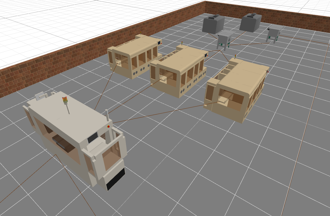
Figure 8.12: 3D Animation of PCB to scale.
We could continue improving our animation with more attention to the detail (perhaps upgrade our “table saw”), but we’ll leave that as an exercise for you. But we’ll come back for some additional enhancements later.
8.2 Entity Movement
We’ve incorporated the movement of entities from one location to another in most of our previous models. In some models you’ve seen the entities moving; in others it’s been an instantaneous movement. In fact there are many ways that an entity (or a “flow” entity) can move in Simio. Table 8.1 illustrates some of the movement alternatives. The easiest and most intuitive alternatives are those using the network capabilities built into the Standard Library. We’ll spend considerable time discussing many of those in the following sections. But we’ll start with a very brief introduction into movements not relying on those networks.
| Free Space | Standard Library | Flow Library | Extras Library |
|---|---|---|---|
| Assign movement | Connector | Container Entity | Crane |
| Transfer step | TimePath | Flow Connector | Robot |
| Travel step | Path | Pipe | Lift truck |
| Conveyor | Elevator | ||
| Vehicle | |||
| Worker |
8.2.1 Entity Movement Through Free Space
While in most cases you’ll want to take advantage of the links for movement support built into the Standard library, there are a few cases where you might want more flexibility. Free Space is the term Simio uses to describe the area of a model that’s not on the network, e.g., the “spaces” between the objects. When an entity isn’t located in a “physical location” (a station, a node, or a link, as illustrated in Figure 8.13, it’s said to be in free space. Entities can exist in free space, can move through free space, and can be animated during that move. The three options under Free Space Movement in Table 8.1 differ primarily by the extent that physical locations and networks are involved.
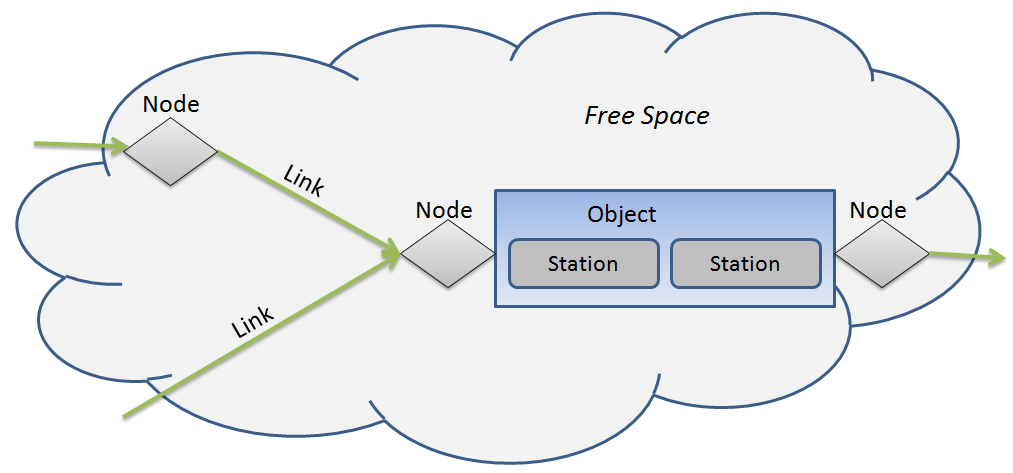
Figure 8.13: Entities can be in a node, a link, a station, or free space.
If you want an off-network instantaneous move, you can use a Transfer step in a process. The Transfer step initiates a (possibly instantaneous) move from a station, a link, a node, or free space to a station, a link, a node, or free space. One somewhat common use for this is in combination with a Create step. When entities are created, they’re created in free space. If you don’t immediately make a change, they may start moving through free space at their default speed. So it’s common to follow a Create step with a Transfer step that initiates transfer into the specified location. Of course, you sometimes want an entity to move through free space without a physical location as its immediate destination. This is particularly common in Agent-Based Modeling (ABM). You can assign an entity’s movement state to specify its location, heading, speed and acceleration. Specifically, you may assign:
- Location parameters: Movement.X, Movement.Y, Movement.Z
- Heading parameters: Movement.Pitch, Movement.Heading, Movement.Roll
- Motion parameters: Movement.Rate, Movement.Acceleration, and Movement.AccelerationDuration
Note that most of these parameters work only in free space and don’t work on links (e.g., don’t try to use these to set acceleration while on a link). But to make this a bit easier, Simio also provides a Travel step which provides the above functionality and more in a somewhat easier to use fashion. Although the entity remains in free space and is not on any network construct, the Travel step may specify that it follows a network. This allows you to control the location as though it is on the network, without having the constraints that accompany traveling on a network. For example acceleration is not supported when on a network, but it is supported when in free space and following a network. One of the additional features provided is to move directly through free space to any absolute or relative coordinate or to any specified object. The Travel step also has a Steering Behavior property of either Direct To Destination or Follow Network Path. The latter can be used to generate behavior similar to natural movements of people down a corridor (e.g., they will disperse themselves across the width of the path and will try to avoid each other).
To make things easier still, the Initial Travel Mode property of any entity (which includes ModelEntitiy, Vehicle, Worker, and ContainerEntity) has three possible values:
Network Onlyindicates that the entity can only travel on a network and will not automatically travel through free space.Free Space Onlyindicates that the entity can only travel through free space and will not automatically travel on a network. As that name might imply, it releases that entity from the constraints of traveling on a network, to instead travel directly from object to object through free space. This can be particularly useful when you have a large number of locations (like a country-wide distribution network) and you don’t need your entities to follow a specific path between locations.Network If Possibleis the default which combines the above and indicates that if the entity can reach its destination by traveling on a network, then it will do so; otherwise it will automatically travel through free space.
The third option is the default option and is why, for example, you can place a Source and a Sink with no connecting link and you will see entities move between them using free space, Network If Possibleis very easy to use, but should be treated with caution. The entity will nearly always be successful reaching its destination - generally a good thing, unless you expect the entity to be constrained to a network and “forgot” to put in a required link. In that case the model will work, but the behavior is wrong and this error may be hard to discover.
Most of the concepts we learned in Section 5.4 about selecting entity destinations still apply with free space moves. Unless you change the defaults, the entity will always move to the closest destination. But you have the complete set of options in Entity Destination Type (i.e., By Sequence, Continue, Select From List, and Specific) available for your use.
For some example models refer to the SimBit FreeSpaceMovement which contains three models illustrating free space movement concepts. You may also refer to the SimBit TravelWithSteeringBehavior for an illustration of how steering behavior works.
8.2.2 Using Connectors, TimePaths, and Paths
As we discussed above, in most cases you’ll be moving your entities across a network using features provided by the Standard Library. The first choice you need to make is whether your entity will be moving by itself (e.g., a person or autonomous object moving on its own), or if it will require assistance to move (e.g., a person, vehicle, conveyor, or other device). The Standard Library options in Table 8.1 will be explored in the next sections. But first let’s discuss what links are and what they have in common.
8.2.2.1 General Link Properties
Simio defines a link as a fixed object representing a pathway between nodes that may be traveled by an entity. There are a lot of concepts buried in that sentence:
- A link is an object. It’s a fixed object, meaning that it can’t move during a run.
- A link connects nodes. It can’t exist by itself or with a single node.
- Entities are the only objects that may travel on link. This sounds more constraining than it is. Vehicles and Workers are also entities (with extra behavior), since they are derived from entities.
Here are a few more concepts common to all links:
- A link must have a start node and an end node.
- A link is a member of one or more networks, which is simply a collection of links. A link is always a member of a special network called the “Global” network.
- A link object has a length that may be separated into equally spaced locations (cells).
- Link control and position are determined by the leading edge of an entity. When an entity’s leading edge moves onto a link, the entity movement is controlled by the logic built into that link.
- Simio provides tracking of the leading and trailing edges of each entity, and detects collision and passing events. This makes it relatively easy to define and customize your own link behavior in processes.
Standard Library link objects include the Connector, Path, TimePath, and Conveyor. Let’s discuss those first three objects next.
8.2.2.2 Connectors
Connectors are the simplest type of link. They connect two objects directly with no internal time delay (e.g., in zero-time). Since the movement is instantaneous there is no interference between entities; in fact, only one entity at a time is traversing the link. It works as though the entity were transferring directly from the start node to the end node, or directly to the object associated with the end node. Connectors have a Selection Weight property that can be used to select between outbound links when more than one outbound link is connected to a node. We used this feature in Model 5-1, discussed in Section 5.2.
8.2.2.3 TimePaths
TimePaths have all of the basic link capabilities including the Selection Weight discussed above. But instead of being a zero-time transfer like a Connector, it has a Travel Time property to designate the time the entity should take to travel the length of the path. It also has a Traveler Capacity so you can limit the number of entities concurrently traveling on the path. Because of that capacity limitation, it also has an Entry Ranking Rule to use in selecting which of the potential waiting entities should be granted access next.
TimePaths also have a Type, which determines the travel direction. This can be either Unidirectional or Bidirectional. Unidirectional allows travel only from the start node to the end node. Bidirectional allows travel in either direction, but only in one direction at a time, much like a one-lane bridge on a two lane road. If you want to model a fully bidirectional path (e.g., a two-lane road) you’d need to model each lane as a separate unidirectional path. For a bidirectional path you can control the direction in your logic by assigning the path state DesiredDirection to:
Enum.TrafficDirection.Forward,
Enum.TrafficDirection.Reverse,
Enum.TrafficDirection.Either, or
Enum.TrafficDirection.None.
Note that TimePaths support State Assignments for On Entering and Before Exiting the path. They also support a set of Add-on Process Triggers to allow you to execute logic at key situations. These are very powerful features for customizing links’ behavior and their interaction with surrounding objects.
8.2.2.4 Paths
The Standard Library Path object has all the features of the TimePath except for the TravelTime property. Instead of that, the Path calculates the travel time based on each individual entity’s DesiredSpeed and the length of the Path (for example, an entity with Desired speed of 2 meters/minute would require at least 3 minutes to traverse a path of 6 meters). There are other parameters that can also affect the travel time. If the Allow Passing parameter is set to False, then if a faster entity catches up to a slower entity, the fast entity will automatically slow to follow (see SimBit VehiclesPassingOnRoadway for an example of this). Also, the path itself may impose a Speed Limit that may prevent the entity from traveling at its Desired Speed.
Path also has a Drawn To Scale property. If you set Drawn To Scale to False, you can specify a logical length that’s different from the drawn length. This is useful in situations where you need an exact length, or in situations where you want to compress the drawn length for animation purposes (e.g., if you’re modeling movement within and between departments, but the departments are a long distance away from each other).
8.2.3 Using Conveyors
8.2.3.1 General Conveyor Concepts
Conveyors are fixed-location devices that move entities across or along the device. Although conveyors are links (like paths), we’re discussing them separately because, unlike the other Standard Library links, a conveyor represents a device. There are many different types of conveyors varying from powered or gravity-fed roller conveyors that you might see handling boxes, to belt conveyors or bucket conveyors that move everything from food to coal, up to overhead power-and-free conveyors like you might see moving appliances or auto bodies. While heavy manufacturing has relied on conveyors for decades, they have also become prominent in light industry and a surprising variety of other applications. The food and consumer-goods industries use sophisticated high-speed conveyors for bottling, canning, and packaging operations. Mail-order and institutional pharmacies use light-duty conveyors to help automate the process of filling prescriptions. Many larger grocery stores even incorporate belt conveyors into their checkout counters.
The Standard Library Conveyor object shares many features with the Path object discussed above, but adds significant new features as well. Current Simio conveyors are not reversible, so there is no Type property — all conveyors move from start node to end node. Conveyors also don’t have a Speed Limit property, having instead a Desired Speed property that indicates the (initial) conveyor speed when it’s moving. And finally, there is no Allow Passing property — passing never occurs on a conveyor because all entities that are moving are traveling the same speed (the speed of the conveyor link).
An entity is either moving at the speed of the conveyor or the entity is stopped. An entity is said to be engaged if its speed (whether moving or stopped) exactly matches the speed of the conveyor. An entity is disengaged if it’s possible for the conveyor to be moving while the entity isn’t moving (e.g., the conveyor is “slipping” under the entity). We’ll discuss more on how that could happen in a moment.
Entity Alignment is a property that determines what is a valid location for an entity to ride on the conveyor. If Entity Alignment is Any Location, then an entity can engage at any location along the link. If Entity Alignment is Cell Location, then you must specify the Number of Cells that the conveyor has — an entity can engage only when its front edge is aligned with a cell boundary. This property is used when there are discrete components to a conveyor, such as buckets on a bucket conveyor or carriers on a power-and-free system.
The Accumulating property determines whether an entity can disengage from the conveyor. If Accumulating is set to False, then every entity on the conveyor is always engaged. If any entity must stop (e.g., it reaches the end) then the conveyor and all entities on it must also stop. If Accumulating is set to True, then when an entity stops at the end, that entity will disengage from the conveyor — while the conveyor and other entities conveying on it may keep moving. As each entity reaches (or “collides with”) the stopped entity in front of it, that entity will also disengage and stop. These entities are said to have accumulated at the end of the conveyor.
The reverse process occurs when the entity at the end moves off the conveyor. The blockage is removed and the second entity will attempt to re-engage. If the Entity Alignment is Any Location, then that attempt will always be immediately successful. If the Entity Alignment is Cell Location, then the second entity must wait until its leading edge is aligned with a cell boundary, then it can re-engage and start moving.
A final way in which a conveyor differs from a Path is that, because a conveyor represents a device, it has Reliability properties (similar to those of a Server, discussed in Section 5.3.4) and it has additional Add-on Process Triggers associated with reliability.
8.2.4 Model 8-2: PCB Assembly with Conveyors
Let’s use some of this new-found knowledge to continue work on our PCB model. All three of the Finepitch placement machines are fed by and deliver to conveyors. And they have no buffer space on inbound or outbound sides — they feed directly from and to the conveyors and Block when the part cannot move on. Select the three Finepitch stations and change the Buffer Capacity of the Output Buffer to 0 (the Input Buffer should have already been 0).
Use Click and Ctrl-click to select all six connectors so we can convert them and configure their properties as a group, then:
- Right click on any object in the group, then select
Convert to Type\(\rightarrow\)Conveyorto convert all six connectors to conveyors. - Change the Desired Speed to
1 Meters per Minute. - We’d like to make it look like a conveyor. We could apply the Simio built-in conveyor path decorators, but they are too large for our use. So we’ll just make the line that represents the conveyor path look more realistic.
- Go to the
Generalcategory \(\rightarrow\)Physical Characteristics\(\rightarrow\)Size\(\rightarrow\)Widthand set it to0.2meters. - Then still having them all selected, go to Link Tools ribbon (if it is not already open). Click the button that opens the Path Decorators selector and chose the Roller. Feel free to experiment with other path decorators to see what you get.
- Go to the
- Since we’re enhancing the looks of our conveyors, now is a good time to adjust the height of the end points so the parts are delivered to the correct point on the connected machines. Use Shift-Drag in the 3D window to move the height of each of the nodes so they attach at the correct height to the machine. Make sure to do this with both the input and output nodes of the machines. If you want to add turn points to the conveyors without having to first delete the existing conveyors, use the
Add Vertexbutton on the Link Tools ribbon and play with different turn point configurations.
The Inspector can store only three parts on his table. All other parts must remain on the incoming conveyors. Set the Inspector InputBuffer to 3. Adjust the Inspection input-buffer queue InputBuffer.Contents so that it’s a short line just large enough to display three parts and arrange it on top of the back edge of the inspector’s table as in Figure 8.14.

Figure 8.14: 3D view illustrating node and queue positioning.
Run the model and study the behavior closely. Notice that, on accumulating conveyors, parts can be stopped at the delivery end, while other parts are still moving along the conveyor. Note that you’ll start to see backups on the Inspector’s incoming conveyors, especially when it goes Off-Shift. And because the FinepitchFastStation has a faster production rate, it tends to back up faster. But that’s exactly the machine that we don’t want to block. Let’s give entities on conveyors servicing faster machines a better priority by changing the entity priority as it enters that conveyor:
- Select the top outbound conveyor and go to the
OnEnteringproperty under State Assignments. Clicking on the ellipses on the far right will bring up a Repeating Property Editor for making assignments. Set the State Variable property toModelEntity.Priorityand set the New Value property to3. - Repeat this procedure with the middle outbound conveyor, only this time set the New Value property to
2. - Select the entry node for Inspection (Input@inspection) and set its Initial Capacity property to
3, one for each conveyor. This allows all three entities (one from each conveyor) to enter the node and be considered for selection by Inspection. Note that they have not yet left the conveyor, but their front edges are in the node. - Select Inspection and change the Ranking Rule to be
Largest Value Firstand the Ranking Expression to beEntity.Priority. This will pull the highest-priority entity from the conveyors first, rather than just selecting the one that’s been waiting the longest.
Actually, when the inspector is Off-Shift, no parts get processed regardless of priority, so this change won’t make much difference in model behavior. But it will help the top conveyor to remain empty and help it get back to empty as quickly as possible, to minimize any blocking of the fastest machine.
We’ve barely explored the available conveyor features. The various properties can be combined to model many different types of conveyors. You can also supplement with add-on processes on the conveyor or surrounding objects to model complex systems, in particular complex merging and diverging situations. And since the Conveyor is implemented entirely in Process logic that’s open for change, you can create your own Conveyor objects with custom behavior.
8.2.5 Using Workers
In the preceding sections we’ve discussed various ways an entity can move from place to place. Assisted entity movement is a rather broad category, including any time an entity needs some constrained resource like a fixture, cart, person, or bus to assist in getting to its destination. In the simplest case, a fixed resource will suffice. If the movement time from the current location of a resource isn’t important and the animation of the movement isn’t important, then just seizing a fixed resource when you need it and releasing it when you’re done might suffice. This same approach is an alternative when all you need is essentially permission or authorization to move (e.g., a traffic-control officer who points to you and gives you permission to drive past).
The more common case that we’ll discuss next is where a transporter is necessary, and the current location and other properties/states of that device are important. The Simio Standard Library provides two objects for just that purpose: Worker and Vehicle. Both Workers and Vehicles are derived from Entity so they have all the capabilities and behaviors of entities, and more. They can move across networks similarly to entities, except that their behavior when reaching a node may be a bit different.
8.2.5.1 Workers
A Worker is an entity with additional capabilities to carry other entities. It’s dynamic, in that the runtime object (the RunSpace) is created during the run. By specifying the Initial Number in System, you can determine how many Worker copies will be available. Each copy (a separate object) would represent an individual, so Worker doesn’t have an Initial Capacity property; nor will it allow assigning a capacity greater than one. Since Worker is intended primarily to represent a person, it doesn’t have device-specific properties like Reliability, but it does support Work Schedules as would normally be followed by a person. Please consult Figure 8.15 as we review some of the key properties of Worker.
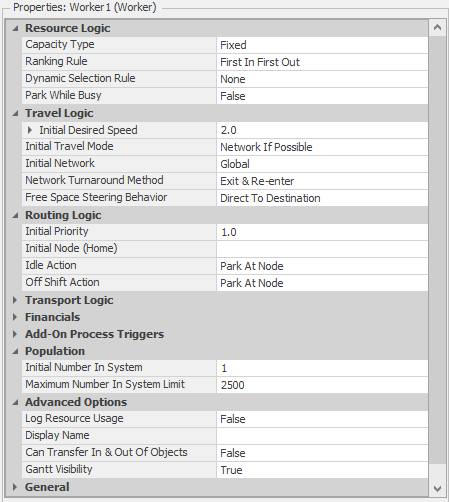
Figure 8.15: Default properties of the Worker object.
Like entities, workers may travel on a designated network or through free space – the default is to follow a network, if possible, otherwise use free space. Under the Routing Logic Category, Workers must be provided a value for Default Node (Home) to specify where on the network the Worker starts and where to return to if directed to its “Home” location. There are two actions that must be specified. Idle Action specifies the action to take when the worker runs out of work and work requests. OffShift Action specifies the action to take when the worker becomes Off-Shift (capacity is zero). For both of these actions, you have two choices. The first choice is whether to remain at your present node location, or return to the designated home-node location. The second choice is whether to Park (move off the network into a parking area that may or may not be animated), or to stay on the network, potentially blocking any traffic that may want to pass.
Under the Transport Logic Category, a Worker has a Ride Capacity that specifies how many entities it can concurrently carry. It also has a Load Time and Unload Time, which determine how long is required per entity for loading and unloading.
Just like an entity, under Population a Worker has a Maximum Number in System, which is provided as a validation tool. You can set this to the maximum number of Workers that you might expect, and if you dynamically create Workers beyond this limit, Simio will generate an error. Under Advanced Options, there is also a Can Transfer In & Out Of Objects property that controls whether a Worker can enter an object through its external nodes (e.g., whether it’s permitted to enter a server). This defaults to False because in most cases Workers may provide a service to an entity or other object, but they usually don’t execute the same processing logic at a server that an entity would.
The Worker has dual modes: as a moveable resource that’s seized and released and travels between model locations, and as a transporter that can pick up, carry, and drop off entities at different locations.
8.2.5.2 Using Worker as a Resource
Workers can be seized and released similar to any other resource object. The Server, Combiner, and Separator objects have provisions for doing that directly, using the Secondary Resources properties. Any standard-library objects can also seize and release resources using the Seize and Release steps in an add-on process. In either case, you’ll ultimately be presented with a Repeating Property Editor similar to Figure 8.16.
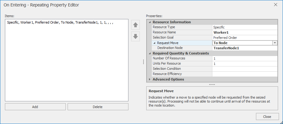
Figure 8.16: Properties used to seize a moveable object.
The simplest use is to leave Object Type set to Specific, meaning that you already know which resource you want. Then enter the name of the object you want (e.g., Worker1) in the Object Name property. Note that, even if you specify the Specific resource, if it’s a transporter (e.g., a Worker or Vehicle), there could be multiple units of that name. Alternately, if you want to select from a set of resources, choose Object Type FromList, which will then allow you to specify the name of a list of resources from which you want to choose.
If you’ve provided more than one possible resource from which to choose, the Advanced Options category provides the rules (Selection Goal and Selection Condition) to select from the choices. The Advanced Options category also allows you to specify the quantity needed, and other options.
If moving the resource to a location is important, you can specify ToNode for the Request Move property, and then the location the resource should visit in the Destination Node property, as illustrated in Figure 8.16. While you may use any node as a destination, it’s often simpler to add a node adjacent to the fixed object, and request that the resource use this new node as a destination for that moveable resource.
Requesting a visit works only for moveable resources – either an Entity or an object derived from an entity like a Worker or Vehicle. When you specify a Request Move, the token will not leave the Seize step until the resource has been seized and moved to the specified node. When the resource is eventually released, it will either get automatically reallocated to another task, or start its Idle or OffShift action if appropriate.
8.2.5.3 Using Worker as a Transporter
A Worker can be thought of as a light-duty Vehicle. It has basic transportation capabilities that permit a Worker to carry or escort one or more entities between locations. Specifying that you want to use a Worker is identical to specifying that you want to use a Vehicle or any type of Transporter:
- Select a
TransferNode(including the transfer nodes on the output side of most Standard Library objects). - In the Transport Logic category, set the property Ride On Transporter to
Always. You’ll see several additional properties displayed. Until you specify which transporter to use, your model will be in an error condition and unable to run. - The Transporter Type property works similar to the Object Type property for resources described above. You can use it to request a specific transporter by name or choose from a list using an appropriate Selection Goal and Selection Condition.
- The Reservation Method specifies how you wish to select and reserve a transporter. There are three possible values:
Reserve Closest— Select the transporter that’s currently the closest and use the Selection Goal to break any ties. Then Reserve that transporter. A Reservation is a two-way commitment: the transporter commits that it will go there (although possibly not immediately), and the entity commits that it will wait for the reserved transporter.Reserve Best— Select the best transporter using the Selection Goal and use the closest to break any ties. Then Reserve that transporter.First Available at Location— Don’t make a reservation, but instead just wait until the first appropriate transporter arrives for a pickup. Note that it’s possible that no transporter will ever arrive unless the transporter is following a sequence (like a bus schedule) or directed via custom logic.
8.2.6 Using Vehicles
A Vehicle is in many ways similar to a Worker. It has the same capability to be seized and released, travel between locations, and to act as a transporter that can pick up, carry, and drop off entities. In fact it has many of the same features. The primary differences are due to its intended use to model a device rather than a person, but it does have a few extra features.
Vehicles have a Routing Type that specifies the routing behavior of the vehicle. If it’s specified as On Demand, then the vehicle will intelligently respond to visit requests, scheduling pickups and dropoffs appropriately. If it’s specified as Fixed Route, then the vehicle will follow a sequence of node visitations (Section 7.1.3). In urban-transportation terminology, On Demand performs like a taxi service, while Fixed Route performs more like a bus or subway.
Vehicles have Reliability Logic, which recognizes that devices often fail. Vehicles can have Calendar Time Based or Event Count Based failures. The latter is extremely flexible. It can respond not only to external events, but you can also trigger internal events based on tracking things like distance traveled, battery-charge state, or other performance criteria.
Beyond the above differences, Vehicles and Workers behave and are used in a similar fashion.
8.2.7 Model 8-3: ED Enhanced with Hospital Staff
Let’s use what we’ve just learned to enhance our Emergency Department model. We’ll start with our ED Model 7-5 (save it as Model 8-3), and enhance it with staffing using Workers. But before we enhance the ED capabilities, let’s make a minor animation improvement. We discussed earlier that the Trauma, Treatment, and Exam-room objects did not represent individual beds, but rather represented areas that could handle multiple patients. While we could certainly enhance the model to represent each bed individually, we don’t yet need that level of detail. Instead let’s just create a slightly better animation symbol to represent a suite of beds.
8.2.7.1 Creating a New Symbol
Your Project name is by default the same as your file name (e.g., Model_08_03). Select the Project name in the navigation window and it will display a window that contains all of your project components. This window allows you to add, remove, and edit your project components. Click on the Symbols icon on the left to view your active symbols. This is where you’d come to edit symbols or to remove unused symbols from your project.
In our case we want to add a symbol:
- Click on
Create New Symbol. This provides a drawing window similar to the Facility window, including 2D and 3D viewing and several familiar ribbons. - We want a room that’s about 10 meters by 3 meters. Use the
Polylinetool to create one four-segment line for the four walls. (Feel free to leave some breaks for doorways if you like, but we didn’t do so.) On the Drawing ribbon set the Object Height to1, the Line Width to0.05, and optionally apply a Texture (we usedBanco Nafin). - We want to put dividers between each patient. Create the first divider, again using the
Polyline. On the Drawing ribbon, set the Object Height to1, the Line Width to0.04, and optionally apply a Texture (we usedDark Green Marble). - Copy and paste your first divider for a total of nine interior dividers, placed one meter apart.
- In the Properties window set the Name property to
HospitalSuite. - With the properties panel collapsed, your symbol should look something like Figure 8.17.
- When you’re done, use the Navigation window to switch back to the Project window or the Model window and your symbol will be automatically saved.
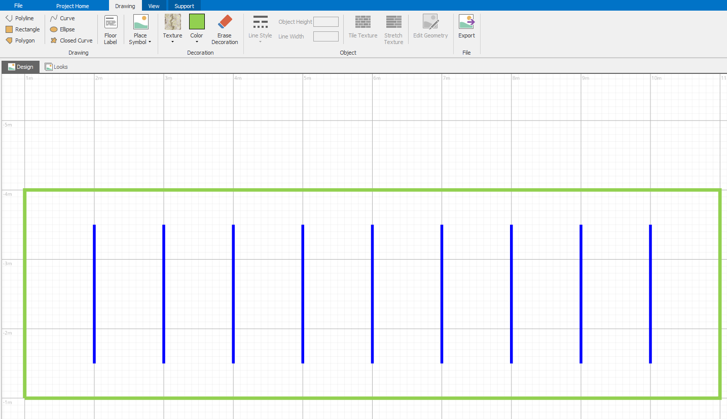
Figure 8.17: Drawing a simple suite of treatment rooms.
The symbol you just created is now part of the project library. Use it to apply new symbols to ExamRooms, TreatmentRooms, and TraumaRooms. Because these are a very different size from the original symbols, we should probably pause and do some related model cleanup (refer to Figure 8.18, for an example):
- Adjust the locations of the objects so the layout looks natural.
- Adjust the node locations so they’re placed outside the objects — perhaps adjacent to any doors if you created them.
- Delete the original paths connecting those objects to others. Replace them with multi-segment paths that are appropriate.
- Adjust the locations of animation queues for each of your rooms: move the
InputBuffer.Contentsto somewhere near your input node, move theOutputBuffer.Contentsnear your output node, and move theProcessing.Contentsso that it stretches across the length of the room. This is a quick way to display the “occupants” in their respective rooms.
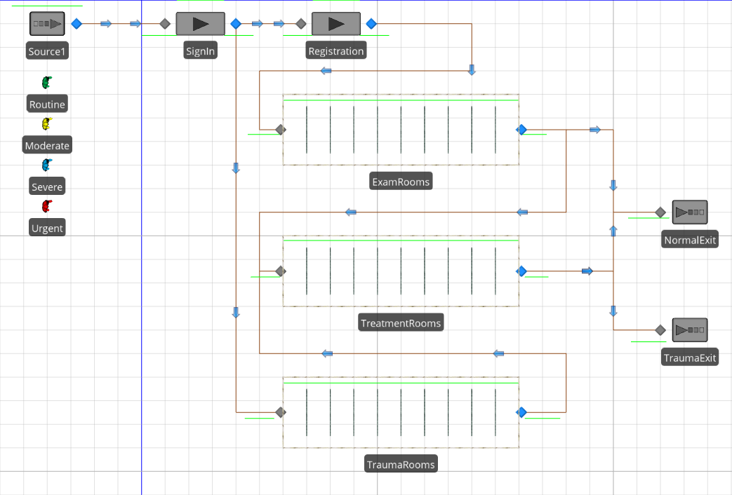
Figure 8.18: Model 8-3 with new object symbols for multi-bed rooms.
8.2.7.2 Updating the Model
Now that we’ve updated the ED layout, we’re in a better position to add the staffing. We’ll model two types of staff; Nurse and Aide. We want all patients to be accompanied to the exam, trauma, and treatment rooms as specified in Table 8.2. Routine patients will wait until an Aide is available. Moderate and Severe patients will be escorted by an aide if available; otherwise they’ll take the first Aide or Nurse who becomes available. Urgent patients will be escorted by a Nurse if available, otherwise by an Aide. All patients will be escorted to the exit by an Aide if available, otherwise a Nurse.
| Patient Type | Exam | Treatment | Trauma | Exit |
|---|---|---|---|---|
| Routine | Aide | – | – | AidePreferred |
| Moderate | AidePreferred | AidePreferred | – | AidePreferred |
| Severe | AidePreferred | AidePreferred | – | AidePreferred |
| Urgent | – | NursePreferred | NursePreferred | AidePreferred |
Let’s start by creating a place for the Workers to call home:
- Draw a 3 by 5-meter Nurses’ station using polylines, as we did earlier. Set the wall height to
1meter. Add a basic node at the entrance; name itNurseStation. - We want to turn off the automatic parking queue for that node and replace it with one we’ll draw inside the nurse-station room. When
NurseStationis selected, select the Appearance ribbon button namedParking Queueto deselect the automatic parking queue. Use theDraw Queuebutton and select theParkingStation.Contentsqueue, then draw the queue inside the room. You can wrap the queue line around the room so you can fit in a “crowd” of nurses if we need them. - Your nurse station should look something like Figure 8.19.
- Repeat the above three steps to create an
AideStationthat will be the home location for the Aides.
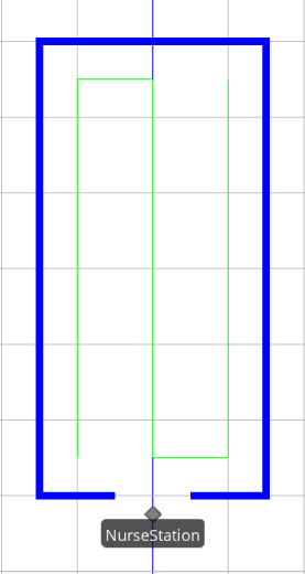
Figure 8.19: Nurse station with node and attached parking queue.
Now let’s create and configure the Workers:
- Place a Worker in your model and name it
Nurse. Set Initial Desired Speed to0.5(Meters per Second). In the Routing Logic category: set Initial Node (Home) toNurseStation; set the Idle Action and Off Shift Action toPark At Home. In the Population category set the Initial Number in System to4to indicate that we will have four nurses. - Place another Worker in your model and name it
Aide. Set Initial Desired Speed to0.5(Meters per Second). In the Routing Logic category: set Initial Node (Home) toAideStation; set the Idle Action and Off Shift Action toPark At Home. In the Population category set the Initial Number in System to6to indicate that we will have six aides.
8.2.7.3 Defining and Using Lists
As we discussed in Section 7.5, a Simio List is a collection of objects that’s referenced when a choice or selection must be made. For example, you may often need to choose between destinations (nodes) or between resources (objects). Selections from a list often support several different mechanisms like Random or Smallest Value, but a common default is Preferred Order, which means select the first one available starting at the top of the list.
Looking at Table 8.2 again, you’ll see that sometimes we need a particular type of worker for an escort (e.g., an Aide), and at other times we want to choose from a preferred order list (e.g., we prefer an Aide if available, otherwise we’ll use a Nurse). Since we’re already using sequence tables to move around, it’s easiest to add this information as a new property (column) in the table. Recall that Workers are a type of transporter, so in this case the property type can be either a transporter or a transporter list. Each property must have just one specific data type, so we’ll make them all transporter lists and just make the list contain exactly one member when there’s no choice. We’ll get back to the table shortly, but let’s first create our lists:
- A list is defined using the Lists panel in the Definitions window. To add a new list you click on the type of list you want to create in the Create section of the List Data ribbon. Referring again to Table 8.2, there are three lists from which we’ll need to choose for an escort: AideOnly, AidePreferred, and NursePreferred. Click on the
Transporterbutton three times to create those three lists, then name themAideOnly,AidePreferred, andNursePreferred. - When you select the
AideOnlylist, the lower part of the screen will display the (currently empty) list of transporters in that list. Click on the right side of the first cell (it may require several clicks) and selectAidefrom the pull-down list of transporters. Since there’s only a single choice in theAideOnlylist, we’re done defining this list. - Repeat the above process for the
AidePreferredlist, puttingAidein the first row andNursein the second row. This list order means that when you select from this list using the Preferred Order rule, you’ll select an Aide if available, otherwise select a Nurse if available. (If neither is available, you’ll select the first one that becomes available.) - Repeat the above process one final time for the
NursePreferredlist, puttingNursein the first row andAidein the second row.
Now that we’ve created our lists, we can add data to our Treatments table. In the Tables panel of the Data window, select the interior tab labeled Treatments. Recall that this table is referenced by the patients to determine which location they should visit next, and what properties to use while traveling to and at that location. This covers all the locations visited, not just the exam-room and treatment locations. We’ll add a property for the transportation:
Click on the
Object Referencebutton and select theTransporter Listtype. Name that propertyEscortType. We’ll use this to specify which worker group from which we want to select for escort to each location. Since not all transfers will require and escort, we also need to set the Required Value property toFalsefor this column so that null values will be allowed.Use the data from Table 8.2 to complete the data in the new column. When completed it should look like Figure 8.20.
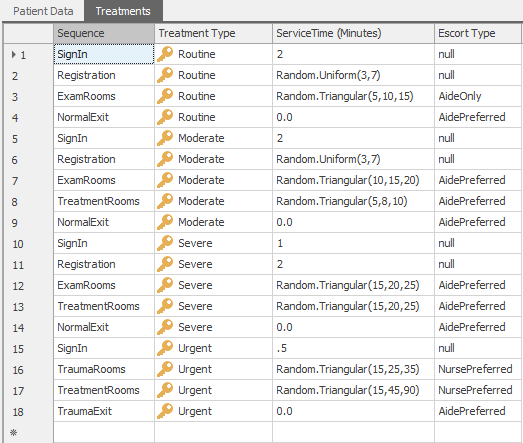
Figure 8.20: Treatment table with escort staff added.
8.2.7.4 Updating the Network and Logic
We’ll finish our enhancements by updating the networks and the logic to take advantage of the staff. Before we start adding to the network, though, we need to make one minor change. Most patients leaving SignIn will go directly to Registration without an escort. For those patients, we need the Ride On Transporter property to be Never. But Urgent patients will need an escort to TraumaRooms and need the Ride on Transporter property set to Always. One easy way to solve this dilemma is simply to have Urgent patients pass through an extra TransferNode adjacent to SignIn. Hence, all patients will leave SignIn without an escort, but Urgent patients will almost immediately pass through a node where they’ll wait for an escort. To make this change, you must delete the existing path from SignIn to TraumaRooms, add a new node adjacent to SignIn (let’s name it WaitUrgentEscort), then add a path from SignIn to WaitUrgentEscort and another from WaitUrgentEscort to TraumaRooms.
Now we’re ready to enhance our network. Although our staff will be escorting patients on the existing network, they’ll also be traveling on their own paths to move between locations. And they need to be able to travel freely from any input or output node to any other input or output node. So we’ll add an additional set of paths to facilitate staff movement.
There are several ways to approach the creation of this network. One extreme approach is to draw two paths (one in each direction) between every pair of nodes. This would obviously be quite tedious, but complete. Another extreme would be to have a unidirectional cycle of paths. This would likely represent the fewest number of paths, but would also result in inefficient and unrealistic movements. We’ll adopt a middle approach — we’ll have a cycle of unidirectional paths, but add extra nodes to support paths to connect the destination nodes as well as support some shortcuts to make travel more efficient.
We’ve added that set of nodes and paths for the “middle approach” as shown in the highlighted paths in Figure 8.21.
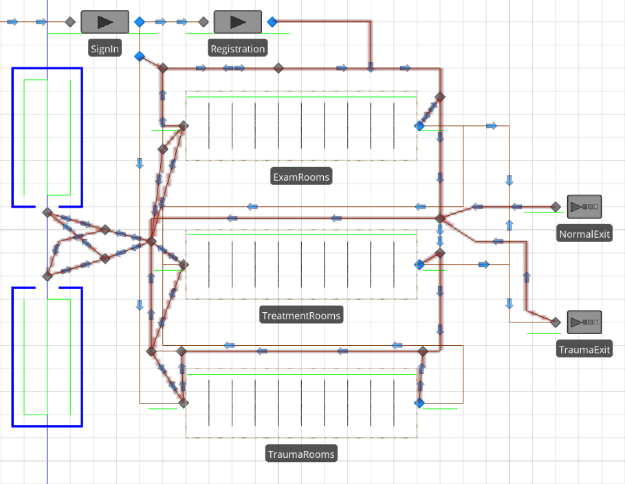
Figure 8.21: Highlighted paths identifying the staff network.
Add paths and nodes to your model in the same fashion. In case you’re wondering, we achieved the highlighting by selecting all the new paths and then right clicking to add them to a network called StaffNetwork. While a network can be used to limit access to only certain entities, in this case we don’t need that capability. But when your path networks start to get complex, assigning them to a named network can be handy for visualization and debugging. To highlight those paths as we’ve done here, go to the Visibility ribbon and select the View Networks button.
So far we’ve created our staff, created lists of them to support selection, added data to our tables so we know what to select, and we now have our paths set up to support escorting. With all that groundwork in place, we just need to tell our entities when to wait for an escort. That’s done on the transfer nodes.
Lets start with our new node, WaitUrgentEscort. Select it and set Ride On Transporter to Always. Set Transporter Type to From List. We want to get the list for this patient and location from our table, so for Transporter List select the value Treatments.EscortType. And finally set the Reservation Method to Reserve Best, leaving the Selection Goal (e.g., how we define “Best”) set to Preferred Order.
Select the three other output nodes where we need escort (Registration, ExamRooms, and TraumaRooms) and make the identical changes to those properties as well. Note that you can do them individually, or do a group-select and then do them all at once.
If you’ve not already done so, now would be a good time to save and run the model. If you’ve done everything right, you should see your patients moving just as they did in earlier versions of this model, but they’ll now be accompanied by staff in some of their movements. You can adjust the location of the RideStation queues on your workers so that the patients travel beside the workers rather than in front of them.
At this point, you’re probably thinking something like — “So what about the actual treatment – are the patients treating themselves? The staff escorts patients, but isn’t involved in patient treatment!” We will add this functionality to the model in Chapter 9. Also, there are many ways that we could enhance the animation and patient movement (the things we focused on in this chapter) but, as authors like to say, we’ll leave such enhancements as an exercise for the reader.
8.3 Summary
In this chapter we have illustrated the value of 2D and 3D animation and some of its uses in verification and communication. We also discussed some pitfalls in placing too much emphasis on animation to the exclusion of higher-priority project tasks and other analysis techniques. We briefly explored many of the basic animation and viewing options to give you a sound basis for animating your own models. Then we discussed how to animate dynamic objects (e.g., entities) when they are moving through free space, on links, on conveyors, or being assisted by other dynamic objects like the Standard Library Worker or Vehicle.
In addition to the above topics there are other modeling situations and approaches that will be discussed in Chapter 10.
8.4 Problems
The goal for the first four problems is to better understand animation issues, not necessarily to generate a useful analysis. To this end, unless otherwise specified you can make up reasonable model parameters to help you illustrate the assigned task.
- Create a new model similar to Model 4-3. Animation is of primary importance in this model, so use what you have learned in this chapter to make it as realistic as possible. For the customers, use multiple animated (walking) people including at least 2 men, 2 women, and 1 child. Use symbols from Trimble 3D Warehouse to add realism.
- The bank in the above problem 1 has decided to add bench seating for customers waiting for the ATM. Enhance the solution to the above problem to add benches, then use an oriented point queue and the animation index to animate the customers seated on the bench while they are waiting. What is the impact of selecting the
Keep In Placeoption on that queue? Change the ATM processing queue to allow the customer to face the ATM while processing and add an appropriate animation index to improve their animated action. - Enhance Model 7-2 by adding a floor label attached to each entity instance to display its Level of Service (elapsed time in system in minutes) and use the background color to indicate patient type. Add one or more floor labels to the model to display in tabular form 3 pieces of information for each patient type:
Number In-Process,Number Processed(those who have left the system), andAverage Level of Servicefor those who have left. - Create a model with three Source–Path–Sink sets that each require a vehicle to move entities from the Source to its associated Sink. Use a custom vehicle symbol from the included library. Try each of the three Network Turnaround Methods and compare and contrast each approach.
- Speedee Car Rentals is open 24 hours and has two classes of customers – 25% are premium customers who are promised a waiting time of less than 5 minutes from when they enter or they will receive a $15 discount on their rental. The others are regular customers who will wait as long as they have to wait. Customers arrive about 2 minutes apart (exponential) and move about 4 meters at 1 mile per hour to either the premium counter (1 agent) or the regular counter (2 agents). All customers have a uniformly distributed service time of from 2 to 7 minutes. Each agent costs $55 per hour (including overhead) and each customer completed contributes $8 to income (minus any discount they might have received). Model this system without using any links. Run for 10 days per replication. For each scenario, report the utilization of each type of agent and the waiting time of each type of customer. Both on-screen and in the output, report the number of premium customers who received a discount, the total discounts paid, and the net profit (after discounts and costs) of the system.
- Scenario a) Assume that each agent only handles customers of his designated type.
- Scenario b) Relax the above assumption. Consider alternate work rules (who services which customer under which conditions) for this same staff. Evaluate each proposed scenario to see the impact on the metrics.
- Scenario c) Model other possible solutions to improve the system. You may use links if that helps.