Simio and Simulation: Modeling, Analysis, Applications - 7th Edition
Chapter 11 Customizing and Extending Simio
In many cases, you will be able to solve your simulation problems using the objects from the Simio Standard Library or by supplementing the individual object instances using add-on processes. But in some cases you may need or want more capability than is offered by that approach. For example:
- You may find that you need more object customization than is easily available using add-on processes.
- You might make repeated use of the same object enhancements and prefer to create your own reusable objects.
- You might have a team of more advanced modelers who support the use of simulation by occasional, less skilled users who merit their own customized tool.
- You may desire to build commercial libraries that you market and sell to others.
All of these may be accomplished by creating custom Simio objects and libraries. If you have read the initial 9 chapters and worked along with the examples, you actually know most of what you need to know in order to define custom objects – the first part of this chapter will bring together concepts you already know and fill in a few missing concepts. Even though custom objects are quite flexible and powerful, a few motivated modelers may desire to go beyond what can be done with objects. Simio also provides additional capabilities for more advanced users. If you have some programming background (like Visual Basic, C++, C#, or any .NET language), you can:
- Write your own design-time add-ons for example to automatically build a model from external data.
- Add new dynamic selection rules to those already available within Simio, for example a comprehensive work selection rule for a Vehicle, Worker, or Server.
- Add custom routines for importing and exporting tables.
- Add custom algorithms for designing (e.g., setting up or analyzing scenarios) or running (e.g., optimizing) experiments.
- Add custom Steps and Elements to extend the capabilities of the Simio engine.
- Customize the Simio ribbons to make it easier for a specific application or even make it look like a totally different product.
An overview of these capabilities is provided near the end of this chapter. Some of the material in this chapter has been adapted from Introduction to Simio (C. D. Pegden and Sturrock 2013) (the e-book included with the Simio software) and used with permission.
11.1 Basic Concepts of Defining Objects
The Standard Library that we have been using up to this point is just one of many possible libraries that you can use to build your models. You can build libraries of objects for your own purposes or build libraries to share across your enterprise. One of the basic principles of Simio is the notion that any model can be an object definition. Models are used to define the basic behavior of an object. It is fairly easy to take a Simio model that you have developed and then “package” it up for someone else to use as a building block for their models. It is also fairly easy to build sub-models within one project and then build your model using these sub-models as building blocks.
The material we will be discussing here is an extension of the Simio process-related ideas we presented earlier in Chapters 4, 5, and 9. In those chapters, we have already learned how to use processes to extend the basic functionality of a specific object instance without altering the core behavior of the object definition. In the next sections our focus will be either on modifying or extending the core behavior of an object definition — thereby changing the behavior of all instances of that object — or on building new objects from scratch.
An object definition has five primary components: properties, states, events, external view, and logic (see Figure 11.1)
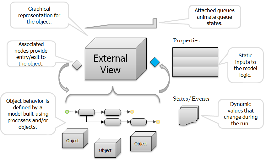
Figure 11.1: Anatomy of an object.
The properties, states, events, and external view are all defined in the Definitions window for a model. The logic is defined in the combination of the Facility and Processes windows for the model.
We initially used model properties to create properties that were referenced in our model and could be used for experimentation. These same properties are used to define inputs for a model when used as an object definition. Model properties provide inputs to model logic and remain static during the run. States are used to define the current state of the object. Anything that can change during the execution of the simulation is represented in the object as a state. Events are logical occurrences at an instant in time such as an entity entering a station or departing a node. Objects may define and fire their own events to notify other objects that something of interest has happened. The External View is a graphical representation for instances of the object. The external view is what someone sees when they place the object in their model. The Logic for the object is simply a model that defines how the object reacts to events. The logic gives the object its behavior. This logic can be built hierarchically using existing objects, or can be defined with graphical process flows.
11.1.1 Model Logic
The logic for a fixed object definition is defined using a facility and/or process model, as determined by the Input Logic Type on the node symbols. In the case of entities, transporters, nodes and links there are no node symbols and hence these models are typically built using process logic.
Whenever you have built a model of a system it represents the logic component of an object definition. You can typically turn any model into a useable object definition by simply adding some properties to supply inputs to the model, along with an external view to provide a graphical representation for the object along with nodes that allow entities to enter and exit the model.
There are three approaches to defining the model logic for an object:
- The first approach is to create your model hierarchically using a facility model. This approach can also be combined with the use of add-on processes to define custom behavior within the facility objects. This approach is typically used for building up higher level facility components such a workcenter comprised of two machines, a worker, and tooling.
- The second and most flexible approach is to create the object definition behavior from scratch using a process model. This is the approach that was used to create the objects in the Standard Library.
- The third approach is to sub-class an existing object definition and then change/extend the behavior of the new object using processes. This approach is typically used when there is an existing object that has behavior similar to the desired object, and can be “tweaked” in terms of property names, descriptions, and behavior to meet the needs of the new object.
11.1.2 External View
The external view is a graphical representation for instances of a fixed or dynamic object. The external view is not used for nodes or links. The external view is defined by clicking on the External panel in the Definitions window for a model as shown in Figure 11.2.
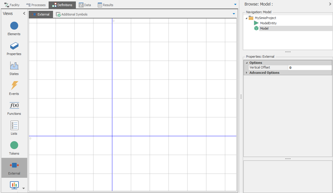
Figure 11.2: External view.
The external view is what a user sees when they place an instance of the object in their model. The graphics for the external view can be composed of symbols from the symbol library or downloaded from Trimble 3D Warehouse, as well as static graphics drawn using the drawing tools on the Drawing ribbon. In addition the view may contain attached animation components that are placed into the view from the Animation window. These animation components include animated queues, status labels, plots, pie charts, linear/circular gauges, and buttons. Note that in the case of dynamic objects (i.e. entities) these animated objects are carried by each dynamic object in the system. For example an entity could carry a status label showing the value of one of its states, or a button that when clicked by the user causes some action to take place (as illustrated in Model 9-2).
When you build a new fixed object you typically provide associated input/output nodes for the object so that dynamic entities may enter and/or leave your fixed object. For example a Server object has associated node objects for input and output. The characteristics of these associated objects are also defined in the external view of the object by placing external node symbols in the external view using the Drawing ribbon. Note that these are not node objects but symbols identifying the location where associated node objects will be created when this object is placed.
When you place a node symbol in the external view you must also define its properties. The Node Class specifies the type of node that should be created. The drop list will give you a choice from all available node definitions which will include Node (empty model), BasicNode (simple intersection), and TransferNode (intersection with support for setting destination and selecting transporters on which entities will ride), as well as any other node definitions that you have loaded as libraries or are defined in your project. In the case of the Standard Library the BasicNode class is always used for input nodes and the TransferNode is used for output nodes. The Input Logic Type specifies how arriving entities attempting to enter this object are to be handled by this object. The None option specifies that entities are not permitted to enter the object. The ProcessStation option specifies that the arriving entity may enter at a specified station, which fires a station-entered event that can be used to trigger process logic. This is used when defining the object logic using a process model. The FacilityNode option specifies that the arriving entity is to be sent to a node inside the facility model for the object. This option is used for defining object logic using a facility model. In the General section the Name for the node symbol is specified. This node symbol name is used to create the name of the associated node object that is created at this symbol location when this object is instantiated using the format NodeSymbolName@ObjectName. For example if the symbol name is Input and the object name is Lathe, the associated object that is automatically created is named Input@Lathe. In the Standard Library the input node symbols are named Input and output node symbols are named Output.
11.1.3 Sub-classing an Object Definition
The basic idea of sub-classing an object definition is that the new object definition that you are building inherits its properties, states, events, and logic from an existing object definition. The sub-classed object will initially have the same properties and behavior of the original object, and if the original object definition is updated, then the sub-classed object will inherit the new behavior. However after sub-classing you can then hide or rename the inherited properties, selectively override portions of the process logic that is inherited, or add additional processes to extend the behavior. For example you might create a new object definition named MRI that is sub-classed from Server and incorporated into a library for modeling health care systems. You might hide some of the normal Server properties (e.g., Capacity Type), and rename others (e.g., rename Process Time to Treatment Time). You might also replace the normal internal process that models a failure by a new process that models the failure pattern for an MRI, while continuing to inherit the other processes from the Server.
To sub-class an object definition, select the Project in the navigation window, and then select the Models panel. The Edit ribbon (Figure 11.3) lets you add a new blank model, create a sub-class of the selected model, or create a sub-class from an object definition from a library. You can also sub-class a library object using the right-click menu on the library object definition from within the Facility window.
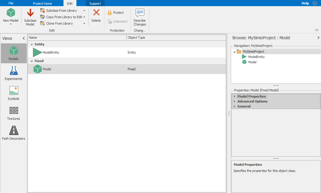
Figure 11.3: Edit ribbon.
A common case for subclassing is when you want set values for multiple properties, possibly involving one or more data tables and then repeat that for multiple similar objects. For example, you may want a set of Servers to get their capacity from one data table and their processing time from another data table. You could do that for each server independently, but it is often much easier to make all the desired changes to a single object instance. After completing your changes on one object instance (e.g., Server1), you can right click on it and select Create Object From This. This will automatically subclass from the Server parent object definition, let you choose a name (e.g., MyServer), and will apply all the properties in the object you are editing to be the defaults in the new object definition.
If you are doing this while building the model, it is not unusual that you might have additional changes that you want to make to an instance – changes that you would like to become part of the object definition and shared across all related instances. Right click on the instance you changed and select the option Update 'MyServer' Property Defaults from This. We will be using this technique in Section 12.13.1 to build Model 12-03.
There are actually three ways to create new objects based on Library Objects:
SubClass From Librarysubclasses (derives) an object from the library object as described above. Changing the original will change the behavior of the sub-classed object since it inherits process logic from its base object definitionCopy From Library for Editcreates a copy of the object without sub-classing. The newly created object definition is a copy of the library object, but does not maintain an inherited relationship; hence if the original object definition is changed the copy is not affected.Clone From Librarycreates an object that is identical to the original (from Simio’s standpoint actually indistinguishable from the original). This should be used when you want to rearrange how models are organized in different libraries.
You can also protect an object definition with a password. In this case the password is required to view or change the internal model for the object.
The model properties include the Model Name, Object Type (fixed, link, node, entity, or transporter), Parent Class (from which this object was sub-classed), Icon for displaying the model, along with the Author, Version number, and Description. The properties also include Resource Object for specifying if the object can be seized and released as a resource, and Runnable to specify if the object can be run as a model or only used as a sub-model within other models.
11.1.4 Properties, States, and Events
Whenever you create an object definition you inherit properties, states, and events from the base object class and you can add new members as well. You can view the inherited properties, states, and events in the Definitions window for the model. The inherited and new members are placed in separate categories that can be independently expanded and collapsed. Figure 11.4 shows the Properties panel for a model type Fixed with a single new property named ReworkTime. Note that this property can be referenced by both the objects and process flows within the model.
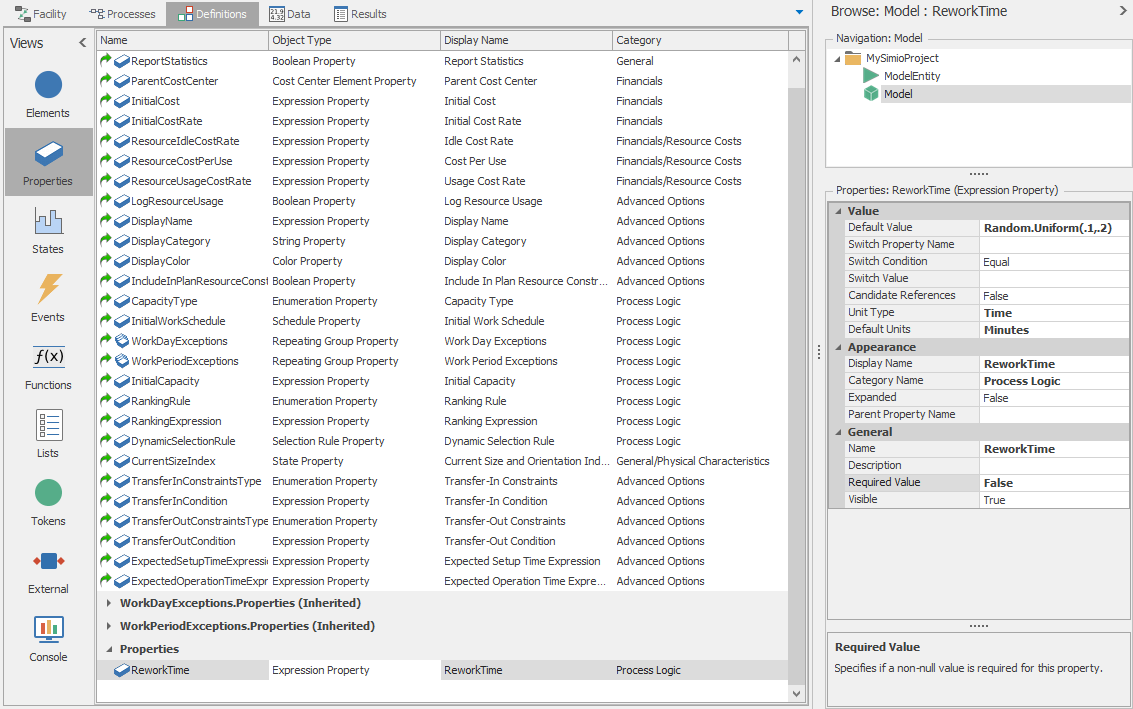
Figure 11.4: Properties panel in Definitions window.
The characteristics of ReworkTime are shown in the Property window, and include the Default Value, Unit Type/Default Units, Display Name, Description, Category Name, and flags specifying if this is a Required Value and if this property is Visible to the user. The characteristics also include a Switch Property Name, Switch Condition, and Switch Value. These can be used to hide or show a property based on the value the user specifies for another property. For example you might have property Y show only if the user sets property X to value greater than 0. This lets you dynamically configure the Property window based on user inputs.
In the case of an inherited property you can change the Visible flag along with the Default Value, Display Name, Description, and Category. Hence you can hide properties or change their general appearance. Although you can add additional states and events to a model you cannot rename or hide inherited states and events.
11.2 Model 11-1: Building a Hierarchical Object
In this example we are going to build a new object definition for a tandem server comprised of two Standard Library Servers in series, with a Connector in between. The first Server has a capacity of 1 and has no output buffer. The second Server also has a capacity of 1 and has no input buffer; hence the second Server will block the first Server whenever it is busy. The object has two properties that specify the processing time on each of the two servers. The object also animates the entity in process at each Server, as well as animating pie charts for the resource state of each Server.
11.2.1 Model Logic
Since we are building this object hierarchically (i.e., from other objects in the Facility Window), we will begin by creating an object and defining its logic in the Facility Window.
- Start with a
New Project. Add a new fixed model from the Project Home ribbon and rename this new model toTandemServer. - Select the
TandemServeras the active model and place two Servers connected by a Connector its Facility window. Set the Output Buffer for Server1 to0, and the Input Buffer for Server2 to0.
Next we will define the properties of our Tandem Server and customize the display of its Properties Window:
- In the Properties panel of the Definitions window add two new Standard Properties of type
Expression. Name themProcessTimeOneandProcessTimeTwo, and set their Default Value, UnitType/Default Units, Display Name, and Category Name as shown in Figure 11.5. - Expand the inherited properties. Since the inherited properties named
CapacityType,WorkSchedule, andInitialCapacityare not relevant for our TandemServer object, set the Visible characteristic in the General category toFalseto hide each of these as shown in Figure 11.6.
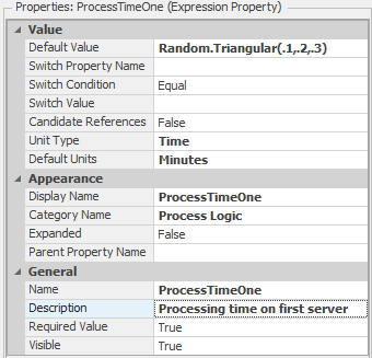
Figure 11.5: Characteristics (properties) of Tandem Server process time one.
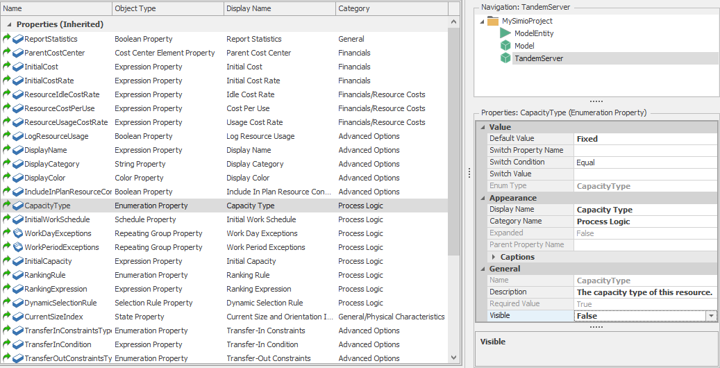
Figure 11.6: Hiding an inherited property.
11.2.2 External View
Next we will use the External View to define what we want users to see when they place the object. Starting with Simio version 4, objects, nodes, links, and status animation that are defined in the Facility Window are automatically added to the external view. This is particularly handy if you want to show entity movement on links that are internal to your object. In our case we want the finer control (and learning experience) of creating our user view manually, so we will start by turning off the default user view.
- Select the
Facilitywindow. To suppress the automatic inclusion of these items in the external view right-click on each item in the Facility View and deselect theExternally Visibleoption. Rather than change each item individually, you can also use the Control-Drag to highlight all of the items and deselect theExternally Visibleoption for all of them at once. - Select the
Externalpanel and place two Server symbols back to back using thePlace Symbol Ribbonbutton. - Place an
External Nodeon the input side, with Node Class specified asBasicNode, Input Location Type set toNode, Node specified asInput@Server1and give it a base Name ofInput. - Using
Queuebutton on the Animation ribbon, draw animated queues for the input buffer, the two processing stations, and the output buffer. As you place each queue select the Alignment ofNoneon the Appearance ribbon. Specify the Queue States asServer1.InputBuffer.Contents,Server1.Processing.Contents,Server2.Processing.Contents, andServer2.OutputBuffer.Contentsrespectively. - Using
Status Piebutton on the Animation ribbon, add two animated pie charts sized approximately 5 by 6 meters each. Specify the Data Type asListStateand List State asServer1.ResourceStateandServer2.ResourceState, respectively. It should look something like shown in Figure 11.7.

Figure 11.7: Defining the external view for Tandem Server.
Note that in our external view we are sending entities arriving to the associated node that is created by the Input node symbol to the node named Input@Server1 in our facility model of the TandemServer. Here they will proceed through the two Servers until they reach the output node of Server2, where we want to send them back up to the associated node defined by the external node symbol named Output. To inform Simio about the external output node, return to the Facility window for TandemServer and right-click on the output node for Server2. From the drop-down menu choose Bind to New External Output Node and specify the External Node Name as Output. This will cause the departing entities to be sent out from the associated output node that is created for the Output. Note that you can return to the External View and move the newly created node to its position on the right side of the second server symbol.
We will also edit the Processing Time for Server1 to be ProcessTimeOne and the Processing Time for Server2 to be ProcessTimeTwo. Do this by right clicking on each Processing Time property, select Set Referenced Property, then select the appropriate property that you defined earlier. Now these processing times will be specified by our newly created properties for TandemServer.
11.2.2.1 Section Summary
In this section we built an object using the hierarchical approach. We specified the object’s logic in the Facility window. We defined the properties that we wanted users to see as well as hid some properties that we did not want users to see. Then we used the External view to define what we want users to see when they place our new object in their Facility window.
We are now ready to use our new object definition. Click on our main model (Model) to make it the active model, and then place a Source, (TandemServer) (selected from the Project Library on the lower left), and Sink, and connect them with Paths. If you click on the TandemServer you will now see our custom properties displayed in the Property window. Figure 11.8 shows our simple model employing our new TandemServer object in operation.
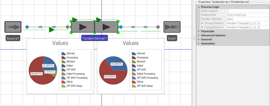
Figure 11.8: Completed Tandem Server in operation.
11.3 Model 11-2: Building a Base Object
In our previous example we built a new object definition using a facility model. We will now build a new object definition using a process model. Our new object will be a lathe (a type of machine tool) that can process one part at a time. Our lathe has an input buffer for holding waiting parts and an output buffer for parts waiting to exit to their next location.
11.3.1 Model Logic
Start with a new project (ModelEntity and Model). Add a new Fixed Class model from the Project Home ribbon and rename it Lathe. Make Lathe the active model and click on the Properties panel in the Definitions window. We will define four new properties for our new object and hide inherited properties that we do not want the user to see:
- Add a new Standard Property of type
Expression. Name itTransferInTime, and set its Default Value to0.0, UnitType toTime, Default Units toMinutes, Display Name toTransfer In Time, and Category Name toProcess Logic. - Add another new Standard Property of type
Expression. Name itProcessingTime, and set its Default Value toRandom.Triangular( 0.1, 0.2, 0.3), UnitType toTime, Default Units toMinutes, Display Name toProcessing Time, and Category Name toProcess Logic. - Add two new Standard Properties of type
Integerfor specifying the buffer sizes. Name themInputBufferCapacity(with display nameInput Buffer) andOutputBufferCapacity(with display nameOutput Buffer). Set their Default Values toInfinityand their Category Names toBuffer Capacity. - Expand the inherited properties. Since the inherited properties named
CapacityType,WorkSchedule, andInitialCapacityare not relevant for our Lathe object, set the Visible characteristic in the General category toFalseto hide each of these just as we did in the previous example (Figure 11.6).
To support building the logic in the Process window, we will first add the stations that we will be using. While still in the Definitions window, click on the Elements panel and add three station elements. Name them InputBuffer, Processing, and OutputBuffer. Use Specify the Initial Capacity for the InputBuffer station as the property named InputBufferCapacity (using the right click, Set Referenced Property approach as we did earlier) and the Initial Capacity for the OutputBuffer station as the property named OutputBufferCapacity. Specify the Initial Capacity for the Processing station as 1.
Navigate to the Process window (still in the Lathe object). Now we will build process flows for moving through each of the three stations we have defined. Entities will enter our Lathe object and the InputBuffer station by executing the process we will name InputBufferTransferIn.
- Click on the
CreateProcess button to create our first process. Name itInputBufferTransferIn. Set the Description to something likeTransfer in from outside the object. Hold the entity until the processing capacity is available. - The token that executes this process is triggered by the
InputBuffer.Enteredevent that is automatically generated each time an entity initiates entry into the station. Set the Triggering Event for the process toInputBuffer.Entered. - Click and drag to add a
Delaystep, anEndTransferstep and aTransferstep to the process. - Set the DelayTime to
TransferInTime, the time each entity requires before its transfer into the station is considered complete. UsingF2, rename the Delay step toTransferringIn. The EndTransfer step signals to the outside world (perhaps a conveyor, robot, person, etc.) that the transfer is now complete. Once the transfer is complete a new transfer can begin as long as there is remaining space in the InputBuffer station. TIP: The step “name” you changed is the unique label given to that step in that process. Using meaningful names not only makes the process easier to understand, but also makes the model trace easier to understand. You should use this feature routinely. - After the transfer in is complete, the token then initiates a transfer of the entity from the InputBuffer station to the Processing station. Set the Transfer step From property to
CurrentStation, the To property toStation, and the Station Name property toProcessing.
The completed InputBufferTransferIn process is shown at the top of Figure 11.9.
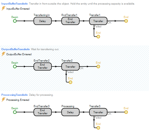
Figure 11.9: Three processes that define the behavior of the Lathe object.
The Processing station executes slightly different logic because it has no transfer in time, but does have a processing time:
- Click on the
CreateProcess button to create our next process. Name itProcessingTransferIn. Set the Description to something likeDelay for processing. - The token that executes this process is triggered by the
Processing.Enteredevent that is automatically generated each time an entity initiates entry into the station. Set the Triggering Event for the process toProcessing.Entered. - Click and drag to add an
EndTransferstep, aDelaystep, and aTransferstep to the process. - The EndTransfer step immediately ends the incoming transfer (there is no transfer-in delay). Once the transfer is complete a new transfer could potentially begin if there were any remaining space in the Processing station. Since the capacity is fixed at one in our object, the next transfer in cannot occur until the current entity has transferred out.
- Set the DelayTime to
ProcessingTime, the time the user has specified for processing. UsingF2, rename the Delay step toProcessing. - After the processing delay is complete, the token then initiates a transfer of the entity from the Processing station to the OutputBuffer station. Set the Transfer step From property to
CurrentStation, the To property toStation, and the Station Name property toOutputBuffer.
The completed ProcessingTransferIn process is shown in bottom of Figure 11.9.
Our shortest and simplest process is for the OutputBuffer station which simply passes the outgoing entity out of the object:
- Click on the
CreateProcess button to create our last process. Name itOutputBufferTransferIn. Set the Description to something likeWait for transferring out. - The token that executes this process is triggered by the
OutputBuffer.Enteredevent that is automatically generated each time an entity initiates entry into the station. Set the Triggering Event for the process toOutputBuffer.Entered. - Click and drag to add an
EndTransferstep and aTransferstep to the process. - The EndTransfer step immediately ends the incoming transfer (there is no transfer-in delay).
- The token initiates a transfer of the entity from the OutputBuffer out through the associated node object that is defined by the ParentExternalNode named
Output. Set the Transfer step From property toCurrentStationand the To property toParentExternalNode. (Note: We will not be able to specify the External Node Name property until we have first defined it in the external view.)
The completed OutputBufferTransferIn process is shown in the middle (shaded) section of Figure 11.9.
11.3.2 External View
Next we will define the external view. Click on the External panel in the Definitions window.
- Place a
Lathesymbol from the symbol library in the center of the external view. - Add an
External Nodefrom the Draw ribbon to the left side of the lathe. Select Node Class ofBasicNodebecause this will be for input only. Name this nodeInput. - Add an
External Nodeto the right side of the lathe. Select Node Class ofTransferNodebecause we want the extended capabilities that offers on the output side. Name itOutput. - Specify the Input Location Type on the Input external node as
Station, and then selectInputBufferfrom the drop list. Note that arriving entities will transfer to the InputBuffer station upon arrival to the associated node object corresponding to this external node symbol. - Add an
Animated Queueto the left of the lathe symbol for animating the InputBuffer station. Specify the Queue State ofInputBuffer.Contents. - Add an
Animated Queueto the right of the lathe for animating the OutputBuffer station. Specify the Queue State ofOutputBuffer.Contents. - Add an
Animated Queueadjacent to the lathe for animating the Processing station. Specify the Queue State ofProcessing.Contents. Use the Shift-Drag technique we learned in Chapter 8 to raise this queue and place it in the throat of the lathe.
Our external view for the Lathe is shown in Figure 11.10.
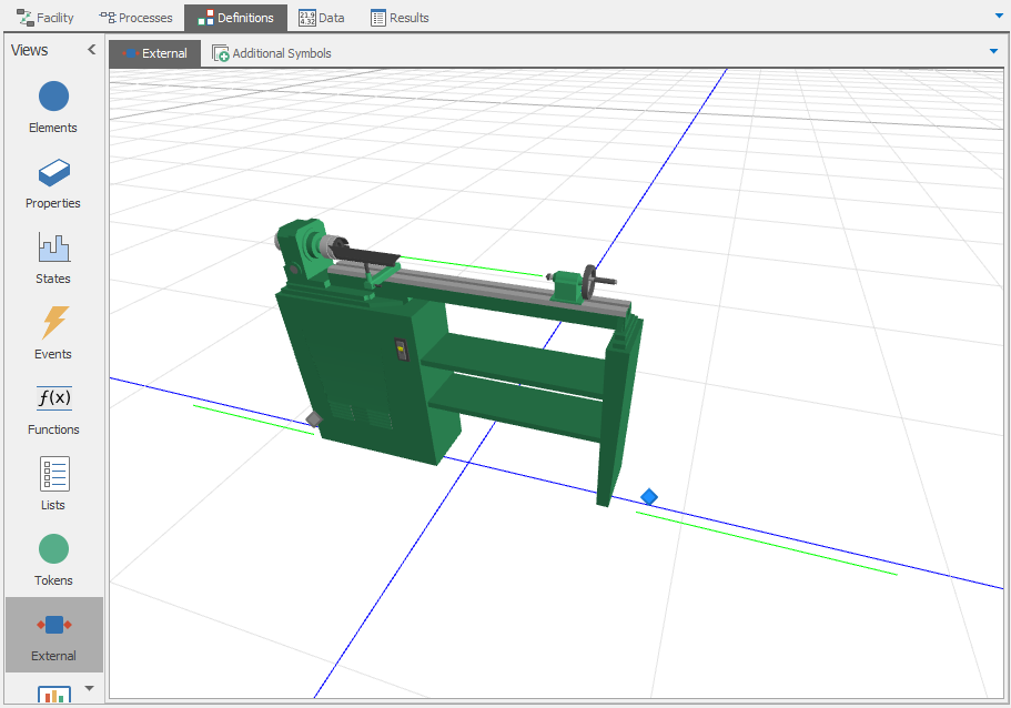
Figure 11.10: External view of lathe object.
Since we have defined our external nodes, we can now go back to the process window and specify our ParentExternalNode named Output on our OutputBuffer Transfer step).
11.3.2.1 Section Summary
We are now ready to use our new object definition in a model. Click on Model in the navigation window to make it our active model and drag out a Source, Lathe (from the Project Library), and Sink, and connect them with Paths. Click on Lathe to edit its properties. You can now run the model to see something like illustrated in Figure 11.11.
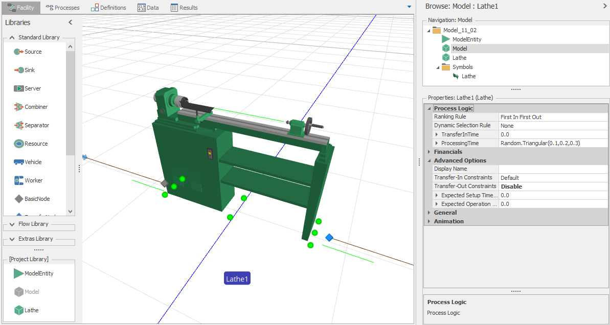
Figure 11.11: Completed lathe object used in a model.
11.4 Model 11-3: Sub-Classing an Object
In this example we are going to build a new object definition named MRI that represents a medical device (a magnetic resonance imaging device). Since this device has many behaviors in common with the Standard Library Server, we will subclass it from Server. We will hide and rename some properties, and add a new property to specify an optional repair person that is required to perform a repair on the MRI. We will then modify the repair logic to seize and release this repair person.
11.4.1 Model Logic
Beginning with a new project we right-click on Server in the Facility window and select Subclass (we could do this same operation in the Project window). This adds a new model to our project named MyServer, which we will rename MRI.
We need to add a new property so that the user can specify which repair person to use:
- Click on
MRIto make it the active model, and then click on thePropertiespanel in the Definitions window. - Add a new
Object Referenceproperty, name itRepairPerson, and specify its category asReliability Logic. - Specify the Switch Property Name as
Failure Type, the Switch Condition asNotEqual, and the Switch Value asNoFailures. Hence this property will not be visible if theNoFailuresoption is selected by the user. - Set the Filter to Resources property to
True - We will also set the Required Value flag to
Falsefor this property.
This property definition is shown in Figure 11.12.

Figure 11.12: Property definition of RepairPerson.
We want to change the terminology used in this object from generic to medical. Change the Display Name of the ProcessingTime property to Treatment Time, and set the Description for this property to The time required to process each patient. The Processing Time property should now look like Figure 11.13.
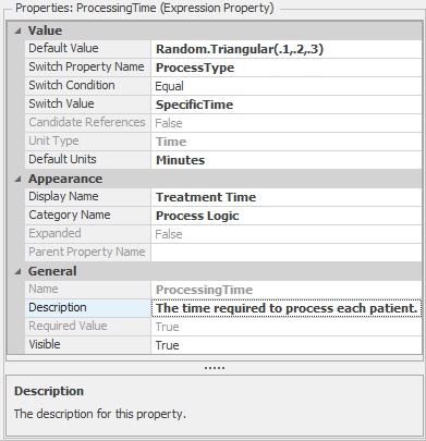
Figure 11.13: Property definition of ProcessingTime to appear as Treatment Time.
We will also hide the inherited properties named Capacity Type, WorkSchedule, and InitialCapacity so they do not clutter the object.
Next we will modify the process logic that we have inherited to make use of the repair person during maintenance. Click on the Processes window to display the inherited processes from the base Server definition. Note that you cannot edit any of the processes at this point because they are owned by the Server and are inherited for use by the MRI. This inheritance is indicated by the green arrow icon on the left that points up. We will select the first inherited process in MRI named FailureOccurrenceLogic and then click on Override in the Process ribbon. This will make a copy of the inherited process from the Server for use by the MRI in place of the same process that is owned by the Server. We can then edit this overridden process in any way that we wish. This override is indicated by the arrow icon on the left that is now pointed down. We could also restore back to the original process by clicking on Restore in the Process ribbon.
Now that we can change the logic in this process, we will add a Seize step immediately before the TimeToRepair delay, and then a Release step immediately after this delay. In both steps we will specify the RepairPerson property as the object to seize/release (use the right-click and Set Reference Property). The beginning of our revised process is shown in Figure 11.14.
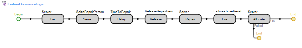
Figure 11.14: FailureOccurrenceLogic overridden to add repair person.
11.4.2 External View
Next we will customize the external view for the MRI. We need to customize the animation in our user view similarly to what we did in previous objects. But we do not need to worry about the nodes and framework because it was inherited from the server object.
Click on the External panel in the Definitions window. In the Place Symbol drop list select Download Symbol to search for and download an MRI graphic from Google Warehouse. Add animated queues for the queue states InputBuffer.Contents, Processing.Contents, and OutputBuffer.Contents. Note that the two external node symbols are inherited from the Server and cannot be modified beyond adjusting their positions.
11.4.2.1 Section Summary
We are now ready to use our new MRI object definition in a model. Click on Model to return to our main model, and drag out a Source, MRI (from the Project Library), and a Sink, and connect them with Paths. Select MRI to edit its properties and then run. Figure 11.15
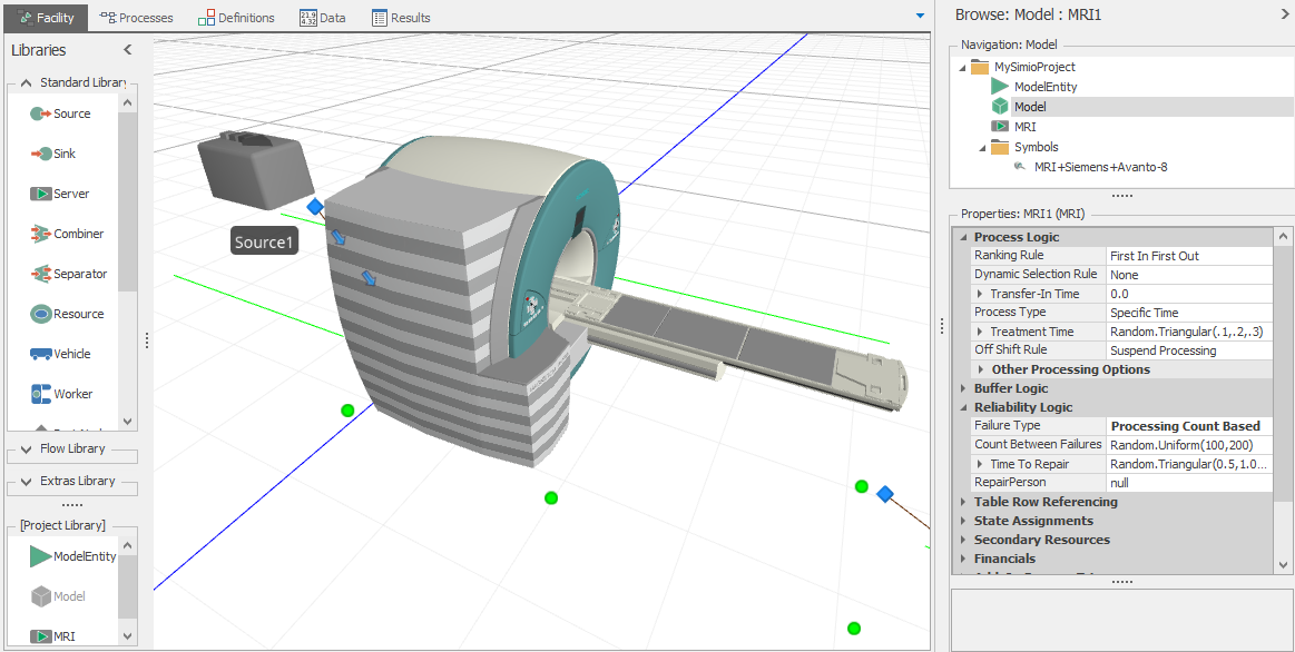
Figure 11.15: New MRI object in use and illustrating custom properties.
11.5 Working With User Extensions
You have already learned to build models using the Standard Library, extend the Standard Library using add-on processes, and (earlier in this chapter) to build your own custom objects. If you have a moderate level of programming skills, Simio goes one step beyond that to allow you to actually extend the underlying simulation engine itself. Simio’s architecture provides many points where users can integrate their own custom functionality written in a .NET language such as Visual C# or Visual Basic .NET.
The types of user extensions supported include:
- User Defined Steps
- User Defined Elements
- User Defined Selection Rules
- Travel Steering Behaviors
- Design Time Add-Ins
- Scheduling Add-Ins
- Table Imports and Binding
- Design or Run Experiments
Simio’s extension points have been exposed as a set of interfaces that describe the methods and calling conventions to be implemented by any user-extended components. This set of interfaces is referred to as the Simio Application Programming Interface (API). For detailed information on the Simio API, see the file Simio API Reference Guide.chm located where Simio was installed (typically C:/Program Files (x86)/Simio).
While you can create extensions using any .NET programming language, Simio provides extra support for C# users. To help you get started creating Simio user extensions, a number of predefined Simio project and project item templates for Microsoft Visual Studio are available. These templates provide reusable and customizable project and item stubs that may be used to accelerate the development process, removing the need to create new projects and items from scratch.
In addition, several user extension examples are included with the Simio installation. You can explore these examples and possibly even customize them to solve your own problems. The examples include:
- Binary Gate - An element and three steps for controlling flow through a gate.
- TextFileReadWrite - An element and two steps for reading and writing text files.
- DbReadWrite – An element and four steps for reading and writing database files
- ExcelGridDataProvider - Supports import and export between tables and Excel files.
- CSVGridDataProvider - Supports import and export between tables and text files.
- SelectBestScenario - Illustrates an experiment data analysis add-in.
- SimioSelectionRules - Contains the implementation of all of Simio’s dynamic selection rules.
- SourceServerSink - Illustrates a design time add-in that builds a simple facility model from code.
- SimioTravelSteeringBehaviors – Supports guidance of entities moving through free space.
- SimioScheduling – Configure resources, lists, and tables for scheduling applications.
These examples can be found in a UserExtensions subfolder of the Simio example models - typically under a Public or All Users folder.
11.5.1 How to Create and Deploy a User Extension
The general recommended steps to create and deploy a user extension are as follows:
- Create a new .NET project in Visual Studio, or add an item to an existing project, using one of the Simio Visual Studio templates. Note that, in addition to the commercial versions of Visual Studio, Microsoft also offers Express and Community editions which are available as free downloads from .
- Complete the implementation of the user extension and then build the .NET assembly (
.dll) file. - To deploy the extension, copy the
.dllfile into the[My Documents]/SimioUserExtensionsfolder. If the folder does not already exist you must create it. As an alternative, you may also copy it to[Simio Installation Directory]/UserExtensions, but ensure that you have proper permission to copy files here.
A correctly deployed extension will automatically appear at the appropriate location in Simio. In some cases these are clearly identified as user add-ins, for example:
- In a model’s Processes Window, all user defined steps will be available from the left hand steps panel under User Defined.
- In a model’s Definitions Window, when defining elements, all user defined elements will be available via the
User Definedbutton in the Elements tab of the ribbon interface.
In other cases it appears as though Simio has new features, for example:
- User defined selection rules are available for use in a model as dynamic selection rules.
- Application add-ins are available for use in a project via the
Select Add-Inbutton in the Project Home tab of the ribbon. - The
Table Imports and Bindingadd-ins are displayed on the Table ribbon under the Bind To button after at least one table has been added.
You can find additional information on this topic by searching the main Simio help for “extensions” or “API”. These topics provide a general overview and introduction to the features. More detailed information is available in the help file Simio API Reference Guide.chm that can be found in the Simio folder under Program Files. This provides over 500 pages of very detailed technical information. Although as of this writing there is no training course provided for creating Simio user extensions, an appendix in the Learning Simio slide set does provide additional step by step instructions. If you are a Simio Insider (which we strongly encourage) you can find additional examples and discussions in the topics Shared Items and API. You can become a Simio Insider at https://forum.simio.com/.
11.6 Summary
In this chapter we have reviewed the basic concepts for building object definitions in Simio. This is a key feature of Simio because it allows non-programmers to build custom objects that are focused on a specific model or application area.
In our examples here we placed our objects from the Project Library. The other alternative is to build the object definitions in their own project and then load that project as a library from the Project Home ribbon.
With Simio you often have the choice to make between working with the Standard Library embellished with add-on processes, and creating a new library with custom logic. If you encounter the same applications over and over again it is more convenient to build custom objects and thereby avoid the repeated need for add-on processes. Of course you can also provide support for add-on processes in your own objects by simply defining a property for the process name and passing that property to an Execute step within your process.
With a bit of experience you will find object building to be a simple and powerful capability for your modeling activities.
11.7 Problems
- Compare and contrast the three ways of creating model logic. What determines your choice when creating a specific object?
- What is the difference between the External View and the Console and what are the limitations of each?
- When you have built a model, say a paint line, what are the typical changes required to make it suitable for reuse as an object in a larger model (e.g., a car plant containing many similar but not identical paint lines)?
- Reproduce Model 11-2, but this time start with a Fixed Class - Processor. What advantages and disadvantages does that approach provide?
- Add a time-based failure to Model 11-2. Provide options for the Time Between Failures, Time To Repair, and optional Repair Resource. Include an external node where the repair operator will come to do the repair. Use this object in a model demonstrating its full capability.
- Create a Palletizer object with one input node for incoming boxes and one output node for the outgoing palletized boxes. Pallets are created on demand within the Palletizer. Boxes can be added to the pallet in a user-specified quantity. Use appropriate animation. Demonstrate your Palletizer object in a model with two types of boxes that cannot be mixed on the same pallet. The full pallets are transported to shipping where the boxes are removed from the pallets and all boxes and pallets are counted.
- Create your own add-in for use in the experiment window. Your add-in should read scenario data from an external data file and then create appropriate scenarios in the Experiment Design view.
- We have a brewing process for which we want to model discrete batch processing. The full system will have many fermentation tanks with long processing times. In order to more easily model the full system we want to create a fermentation tank object. We will consider a small subset of that system to make testing easier. Our subset of the brewing process generates batches of beer according to the schedule in Figure 11.16. Each batch in our test system takes a nominal 2 hours to ferment. (Note: The real system requires many days to ferment). Our fermentation tank can accept up to two batches of the same beer as long as the second batch arrives within 60 minutes of the first batch. Both batches will finish at the time the first batch would have finished alone. Different beer types can never be fermented together. Create a FermentationTank object with the above characteristics and then test it in a simple model with arrivals driven by the schedule in Figure 11.16 and a single fermentation tank for processing. Verify that your object produces the outcome specified in the table comment.
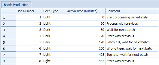
Figure 11.16: Arrival schedule of brewery batches (test data).