Simulation Modeling with Simio - 6th Edition
Chapter
14
A Mobile Resource: The Worker
The previous chapter illustrated the flexibility of Resources andResource Lists to model very complicated relationships. However, these types of resources were fixed because they did not move dynamically throughout the system model. When the patients needed an X-ray, the vets were not released, and the patient moved to the X-ray machine room, but the animation did not show the resources moving along with the patient. Also, in the DMV problem, resources were used in multiple locations, but the travel time between the two locations was not considered. SIMIO has the ability to have multiple types of objects (i.e., entities, workers, and vehicles) that can act as resources (i.e., objects that can be seized and released) and move throughout the system, similar to an entity.
14.1 Routing Patients
Again, we return to the veterinary clinic. However, this time, the clinic will behave more consistently with a doctor’s office where patients arrive, check-in at the front desk, and then wait in the waiting room for an available room. The patients will move to one of four examination rooms once one becomes available. Then, one veterinarian will start from their office, dynamically move to the rooms as needed, and service the patients as requested. The veterinarian will be modeled as a movable resource that needs to be seized and released.
14.1.1 Create a new model that contains oneSource (SrcPatients), aSink (SnkExit), and five Servers (SrvVetWaiting, SrvRoom1, SrvRoom2, SrvRoom3, and SrvRoom4).
14.1.2 Insert a newModelEntity named EntPatients into the model. The patients travel at a constant rate of 4.5 km per hour or 4500 meters per hour.
14.1.3 Insert theServer rooms into a two-hall configuration, with the waiting room serving the two hallways, as seen inFigure 14.1.201
- The capacities of all the servers should be one.
- The check-in process at the SrvVetWaiting uniformly takes between one and four minutes before they are placed into the waiting room.
- Each patient takes between 10 and 20 minutes to be seen, most of which take 12 minutes.
- It has been observed that patients arrive exponentially with an interarrival time of 6.5 minutes.
14.1.4 Insert a wall in the middle of the rooms to add a more visual cue for the hallwayServers separation, as seen inFigure 14.1.202 Make sure to specify a height of 3.5 meters and a width of one meter and give the wall a texture. You will notice we inserted a different line (i.e., window texture) around the waiting room, plus added a 3-D door as the entrance.
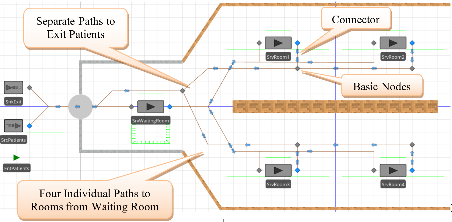
Figure 14.1: New Veterinary Clinic Model for Moveable Resources
14.1.5 Connect the output of the SrvVetWaiting to each of the inputs to the four rooms using fourPaths named PathRoom1, PathRoom2, PathRoom3, and PathRoom4, respectively.
- The distance between the waiting room and patient rooms one and three is 15 meters; it is 30 meters for the other rooms.
- Select all fourPaths and set the traveler capacity to one and the speed to 4.5 kilometers per hour.
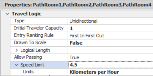
Figure 14.2: Setting up the Patient Entrance Paths
14.1.6 Next, provide a means for the patients to leave the examining rooms and exit the clinic using paths and the same distances from the waiting room to the rooms for the rooms to the exit. BasicNodes can be used to assist in directing the patients out, as seen inFigure 14.1.203 We can use common exit paths (i.e., paths between rooms one and two and four and three) for the output since we do not need to constrain the paths to only have one person traveling on them, as was the case with the input paths.
14.1.7 Connect theSource (SrcPatients) via a 10-meter Path to the SrvVetWaiting and use a 10-meter Path to connect the lastBasicNode to the SnkExit.
14.1.8 Modify theOutputbuffer.Contents queue of the SrvVetWaiting server to have an Oriented Point alignment with several locations with the Keep in Place option checked which will improve the animation.
14.1.9 As before, patients should select a room that is currently available. Create a new node list via the Definitions tab named ListRooms, allowing patients to choose an available room.Figure 14.3 shows the list, noting the order of preference is one, three, two, and then four (i.e., fill up the closest rooms first if more than one room is available).
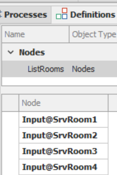
Figure 14.3: Creating a Node List of Examination Rooms
14.1.10 For the outputTransferNode of the waiting room (Output@SrvVetWaiting), specify the Entity Destination Type to select a node “From a list” using the ListRooms as the Node List Name property. The goal is to route patients to an available room. Therefore, specify the Selection Goal as the “Smallest Value.” In previous chapters, we used an expression to determine the total number of entities routing to the input node, waiting in the input buffer, plus those currently being processed by the server.
14.1.11 However, a series of AssociatedStation204 functions (see Table 14.1) can be used as part of the dynamic routing selection for all fixed objects that have external input nodes (e.g., Servers). These external input nodes are associated with an internalStation (e.g., Input@SrvRoom1 is associated with the input buffer station of SrvRoom1).
This function returns the location’s capacity inside the associated object (e.g., the input buffer capacity of the server).
| Function | Description |
|---|---|
| AssociatedStation.Capacity | This function returns the location’s capacity inside the associated object (e.g., the input buffer capacity of the server). 205 |
| AssociatedStation.Capacity. Remaining | This function returns the current available unused capacity of the server’s input buffer. |
| AssociatedStation.Contents | This function will return the current number of entities in the location (e.g., the number in the input buffer of a server (InputBuffer.Contents).206 |
| AssociatedStation.EntryQueue. NumberWaiting | This function will return the current number of entities waiting to enter the location (InputBuffer.EntryQueue). |
| AssociatedStationLoad | This function will return the “load,” which is the sum of entities on their way to the node, waiting to enter and being processed (i.e., input buffer and processing stations). |
| AssociatedStationOverload | This function returns how much a location is overloaded, which equals the “Load” minus “Capacity,” which can be both positive (overloaded) or negative (underloaded). |
Use the expression (Candidate.Node.AssociatedStationload), which returns the total number of entities heading to the room, waiting to enter the room, waiting at the room plus the current number of entities being processed by the room as the Selection Expression property as seen in Figure 14.4.
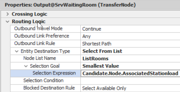
Figure 14.4: Specifying the Selection Expression to Choose the Room with the Smallest Number of Patients
14.1.13 Patients seem to wait by the examining rooms after being checked in instead of in the waiting room, which was different than what was intended. Therefore, we need to force the patients to wait in the waiting room until a room is available in a similar fashion as was done in Chapter 13. Select each of the rooms and change the Input Buffer207 capacity to “0”. Select the output node of the SrvVetWaiting (i.e., Output@SrvVetWaiting) and make sure the Blocked Destination Rule is set to “Select Available Only.”
14.1.14 Run the model to observe what happens. You might need to increase the arrival rate to see if there are any issues (i.e., set the interarrival rate to 0.5) and reduce the processing time in the waiting room.
14.1.14.1 Does the model behave the way it was intended, or are there animation issues still present?\newline
_______________________________________________
The patients will now wait properly in the waiting room since the input buffer capacity is zero, which prevents patients from heading and waiting outside the room doors.
14.2 Using a Worker as a Resource
The current model addresses the exam rooms but does not model the veterinarians. A fixedResource object similar to previous chapters could be used to constrain the processing to only one staff member, but the object is stationary. Since the veterinarian needs to travel between rooms, a dynamic moving resource would better reflect the real system.Workers (andVehicles) in the system can be specified as resources (i.e., they can be seized and released like fixed Resources), but they can also travel throughout the network to service.
14.2.1 Insert a newTransferNode named TOffice to represent the vet’s office at the end of the wall near rooms two and four.
14.2.2 From the [Project Library], insert a new Worker named WkrVet. Change the symbol of theWorker to an appropriate figure if you would like. Modify the properties as specified inFigure 14.5.
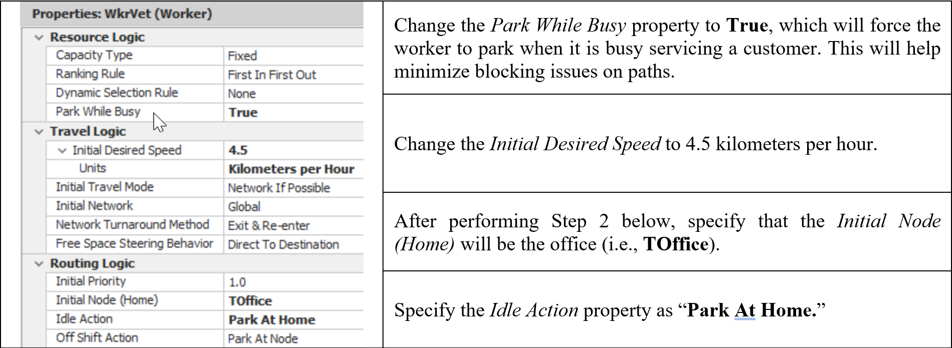
Figure 14.5: Specifying the Worker Properties
14.2.3 If you run the model now, the WkrVet will stay in its office but not actively seek any patients. The patients will need to request the WkrVet in order to be served. When the patient goes into processing, they need to seize the WkrVet and then release it once they have finished processing.208
- From the Processes tab, create a new process named SiezeVet and insert a Seize step that will request a WkrVet to service a patient, as seen inFigure 14.6. Select all four room servers and select the new process SeizeVet as the Before Processing Add-on process trigger.
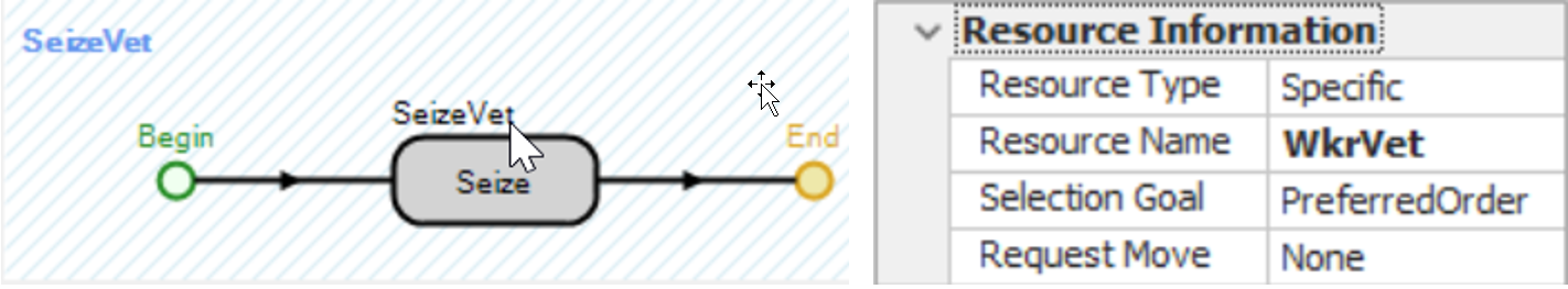
Figure 14.6: Seizing the Worker
- Create a new Process called ReleaseVet. It will be triggered in the Add-on process trigger “After Processing.” Insert a Release step that will release the Vet to service a new patient, as seen in Figure 14.7.
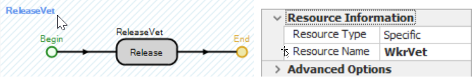
Figure 14.7: Releasing the Worker
- In the dropdown list for the “After Processing” Add-on process trigger for all four rooms, just select the ReleaseVet process to release the veterinarian after the processing has finished.
14.2.4 Save and run the model and observe the veterinarian.
14.2.4.1 Does the vet get seized and released correctly, and does the vet move to the appropriate room?
_______________________________________________
14.2.4.2 Did you notice any animation issues with the patients in the room?
_______________________________________________
Figure 14.8 shows an animation issue of patient 45 waiting for a vet potentially in two places, which did not occur in the previous models. In those models, theservers were the only constraining resource, but suppose we now need a room (i.e., the Server) and a vet (aResource). When we try to seize the vet (a resource) in the Before Processing add-on process trigger, and the input buffer is zero, the entity can become stuck in a limbo state if the room (i.e.,Server) is available but the vet is not immediately available. Thus, the entity cannot enter the input buffer because its capacity is zero, and the vet is unavailable yet has seized the Server’s capacity. The entity has not been completely transferred into the processing station. An entity waiting for a station capacity (in this case, the input buffer) to become available will wait in an “Entry Queue.” Entry queues are used whenever an entity cannot enter a station because there is no capacity available. The animation anomaly occurs because the entity is waiting in the entry queue and has not completely transferred into the processing station owing to the need for secondary resources.
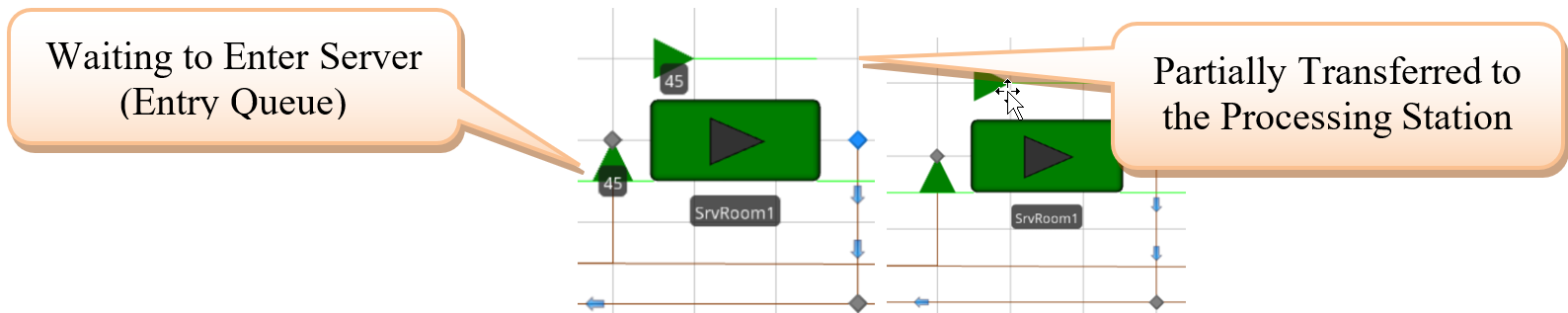
Figure 14.8: Animation Anomalies
14.2.5 We could change the seizing of the vet to occur in the “Processing” add-on process trigger, which happens after the entity has been completely transferred into the processing station. If you want to try it, select SrvRoom1, remove the Before Processing209 Add-on process trigger, and then select the same process from the dropdown of the Processing add-on process trigger. Run the model and observe what happens in the room.
14.2.6 The animation anomaly has been removed, but the patient now waits in the processing station for the vet, which is processed when the vet arrives. However, this can be confusing and cause issues with statistics since both waiting and processing are combined now. Table 14.2 describes the options for choosing a ModelEntity’s destination node from a list. The Selection Condition and Blocked Destination Rule properties can be used to control which nodes are available for possible selection as the destination node.
| Routing Logic | Description |
|---|---|
| Selection Goal | The goal determines the logic to utilize when selecting a destination node for an Entity. This can be random or cyclic (i.e., select the next node in the list), preferred (i.e., always choose the first nodes in the list unless a Selection Condition eliminates a node), smallest and largest distance, and smallest and largest values. |
| Selection Expression | An expression is evaluated for each candidate node destination when the Selection Goal property is set to the “Smallest or Largest Value.” |
| Selection Condition | An optional condition that is evaluated for each candidate destination node. This expression must evaluate to true for the node to be considered under the Selection Goal. |
| Blocked Destination Rule | Determines what happens if the destination nodes are blocked. The default value, “Select Available Only,” will only evaluate nodes to be selected that are currently not blocked, while “Select Any” will select any node regardless of whether it is blocked or not based on the Selection Goal. The “Preferred Available” will first select among all non-blocked nodes and, if all the nodes are blocked, will revert back to select any. A node is considered blocked if the node is an input node of an object and the number of entities assigned to the station is greater than or equal to the capacity of the object (i.e., AssociatedStationLoad >= AssociatedStation.Capacity). |
Table 14.3 looks at all possible scenarios associated with the server’s input buffer size and the values of the Selection Condition and Blocked Destination Rule of theTransferNode. The “Modeling Result” column represents what happens to the additional entities when the rooms all currently have one patient. The Selection Condition will eliminate all nodes (i.e., filter the list) that do not meet the criteria before the selection goal is used, while the Blocked Destination Rule may not allow the node from being selected if the node is currently blocked even though it was not filtered out.
| Input Buffer Cap. | Path Travel Capacity | TransferNode’s Blocked Destination Rule | TransferNode’s Selection Condition | Modeling Result |
|---|---|---|---|---|
| Infinity | 1, Infinity | Any Rule | None | All Entities will Wait at the Server’s Input Buffer. |
| Infinity | 1, Infinity | Any Rule | Candidate.Node. AssociatedStationload ==0 | All Entities will wait at the TransferNode (i.e., Waiting Room) |
| 0 | 1, Infinity | Select Available Only | None | All Entities will wait at the TransferNode (i.e., Waiting Room) |
| 0 | Infinity | Prefer Available, Select Any | None | All Entities will wait at the Server’s Input Node waiting to go into Server. |
| 0 | 1 | Prefer Available, Select Any | None | One additional Entity will wait at the Server’s Input Node, while all others will wait at the TransferNode. |
14.2.7 Set all the Input Buffer capacities of the rooms back to at least one or “Infinity” to allow one entity to wait in the room. Also, reset SrvRoom3’s Before Processing and Processing add-on process triggers back to SeizeVet and nothing, respectively.
14.2.8 From Table 14.3, relying on blocking the node’s associated station alone may be problematic. Therefore, we will set the Output@SrvWaitingRoom’s Selection Condition property to be Candidate.Node.AssociatedStationLoad == 0, which says only nodes with no entities routing to them or currently in the server are eligible to be selected.
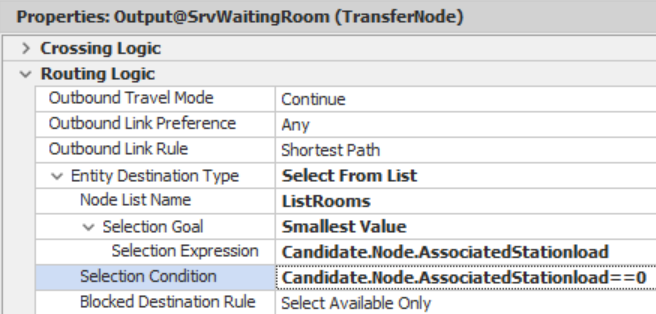
Figure 14.9: Forcing Patients to Wait Until a Room is Available
14.3 Using a Worker as a Moveable Resource
In this case, even though we modeled the veterinarian as a Worker, it acted like a stationaryResource since we did not request that the vet move to the room to service the patient.Workers, likeEntities and Vehicles, are dynamic objects that can move throughout a network. Our vet is now being seized and released, constraining the processing of patients rather than assuming four stationary vets in each room. However, the vet is servicing the patients from the TOffice node. We do not want to seize the WkrVet worker until the vet is in the room.
14.3.1 Create a separate network for the veterinary staff to move throughout the system. Add five additionalTransferNodes named TRoom1, TRoom2, TRoom3, TRoom4, and TWaitRoom. The TRoom nodes should be located near the same room as the office in the back, as seen inFigure 14.10. Having a separate network from patients can be advantageous in not causing bottlenecks, etc. However, in the next chapter, we will need them to travel on the same network of paths to allow theWorker to act like a vehicle.
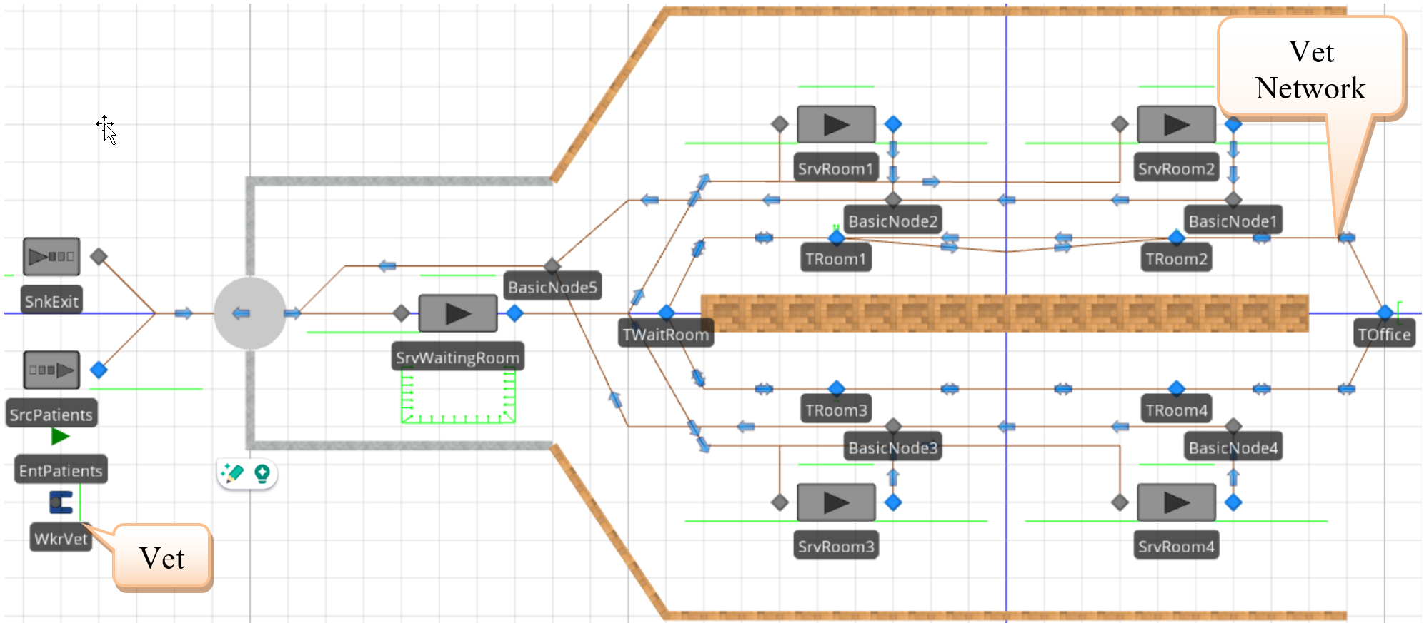
Figure 14.10: Modified Vet Clinic with Vet Network
14.3.2 Connect the nodes using two unidirectional Paths(i.e., one forward and one backward) since the staff can move in either direction to service the next patient. Use logical distances of 15 meters for each link.210 The staff will travel on the inner loop.
14.3.4 FromFigure 14.6 you will notice the Request Move property, which can be changed to “ToNode” and then specify the appropriate destination node (e.g., TRoom1 for room one). This will force the WkrVet to move to the TRoom1Transfernode before processing. The Move Priority property can be used to specify the priority if multiple patients have requested the worker. A tokenized process will be used since the SeizeVet process is the same for all rooms, except the node will change (i.e., TRoom1 to TRoom2).
- Add a newToken named TknVet from the Definitions tab that will have a Node Object Reference state variable named TStaWhichNode that will allow us to pass in the correct node, as seen inFigure 14.11.
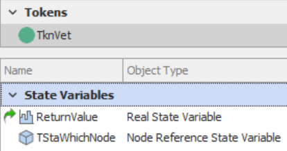
Figure 14.11: Creating a Specialized Token to Pass in the Move Node
- To create the Tokenized process, select the SeizeVet process from the Processes tab and specify the TknVet as the Token Class Name property value, as seen inFigure 14.12. Specify one input argument that allows the user to pass into the process which room needs the service.
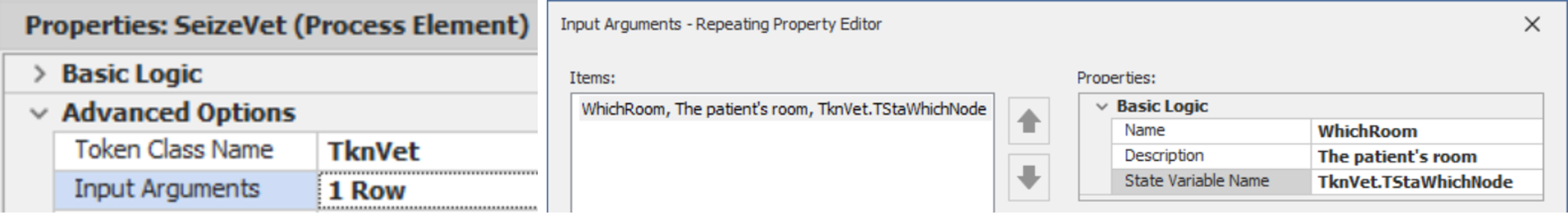
Figure 14.12: Making the SeizeVet Process Tokenized by Passing in one Input Argument
- Next, modify the Seize step to specify the Request Move to a particular node, and the Destination Node will be the TknVet.TStaWhichNode. This will force the vet to move to a particular node before processing can begin on the patient, considering the travel time to the room.
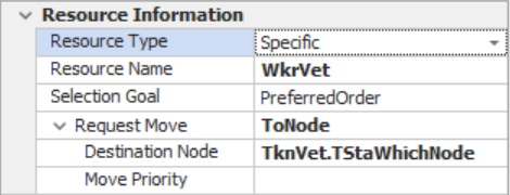
Figure 14.13: Modify the Seize to force Vet to Move to the Specified Node
- Finally, on each of the rooms, specify the appropriate Which Room input argument property for the Before Processing add-on process trigger, as seen inFigure 14.14 for SrvRoom1.
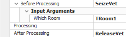
Figure 14.14: Specify the Correct Node Associated with each Room
14.3.6 Add a second veterinary staff member by changing the Initial Numberin the System property under the Population property category to two.212
14.4 Returning to the Office between Patients
One additional modeling concern is that veterinarians need to return to their office after each visit to complete paperwork on the current patient and look over the next patient’s chart. All this needs to be done before returning to one of the rooms to service the next patient. So we need to force them to go back to the office and delay for a particular time before returning to service the next patient. Since resources respond to requests to be allocated (i.e., patients trying to seize them), one can model the situation where an entity requests the WkrVet at the office so they will return to the office and process that paperwork entity. In the office, the paperwork uniformly takes between four and fourteen minutes.
14.4.1 Save the current model as a new model and set the number of available veterinaries back to one.
14.4.2 Insert aServer named SrvOffice near the TOffice transfer node and connect it to aSink called SnkOfficeWork via a connector as seen inFigure 14.15. Specify the processing time in the SrvOffice as Uniform(4,14) minutes.
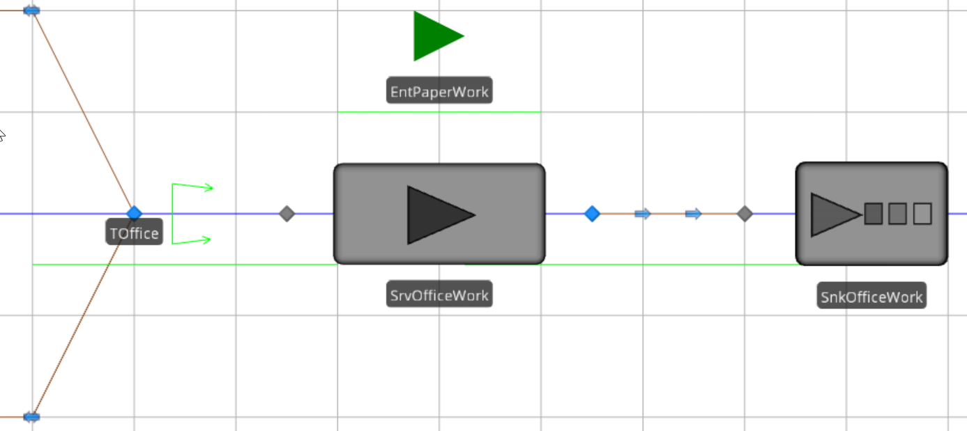
Figure 14.15: Modeling the Paperwork
14.4.3 Insert a newModelEntity called EntPaperWork. It will be this entity that is processed in the office. Since we want the Vet to do the paperwork before seeing any other patient, let’s give the Initial Priority of the EntPaperWork a value of “2” (recall that the default value is “1”). Then to ensure that this paperwork is given priority, change the Dynamic Selection Rule property of the WkrVet to “Largest Value First,” with the Value Expression as Candidate.Entity.Priority.213
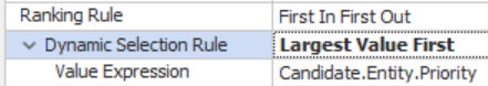
Figure 14.16: Changing the Dynamic Selection Rule of the Worker
14.4.4 When the vet finishes at a room, paperwork needs to be created and sent to the office. This paperwork needs to Seize the WkrVet before another room seizes the vet. Also, as a part of this process, the vet must be released from the room to visit the office. Therefore, we need to modify the ReleaseVet process to accomplish all this, as shown inFigure 14.17. Recall that this process is used by all the rooms when patients exit.
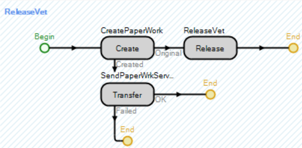
Figure 14.17: Creating and Transferring the Paperwork
- Use the Create step to generate a paperwork entity and a new Token associated with the new entity.
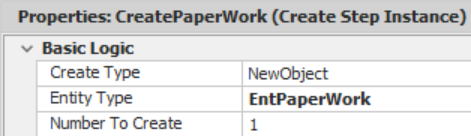
Figure 14.18: Create Step to Produce an ModelEntity
- Use the Transfer step to send the paperwork entity to the input buffer station of the officeServer.214
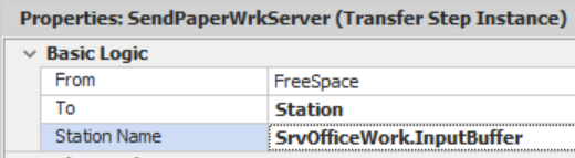
Figure 14.19: Using the Transfer Step to move the New Paper ModelEntity
14.4.5 For the SrvOffice, create two new add-on process triggers processes for Before Processing and After Processing.

Figure 14.20: Requesting and Freeing the Vet from Paper Work at the Office
- Copy the Seize step from one of the four rooms to request the WkrVet for the paperwork. Remember to change the node to visit the Toffice node in the Seize step.
- Copy the Release step from ReleaseVet to release the Vet after the paperwork is finished.
14.4.7 The issue seems that the vet will process a second patient before heading back to the office. Essentially, the vet processes the previous patient’s paperwork, but it is difficult to determine which paperwork went with which patient since all the patients and paperwork entities are green. To alleviate the situation, add three additional symbols for both the EntPatients and EntPaperWork, giving each one of the additional symbols a different color and making sure the symbols for each entity type are the same color (i.e., 0th symbol is green for both patient and paperwork, 1st symbol is red for both, 2nd symbol is yellow, and the 3rd symbol is blue).
14.4.8 Patients will be assigned a color based on the room they are serviced in (i.e., patients will be green in Room 1, red in Room 2, yellow in Room 3, and finally blue in Room 4). Since this will be done when the patient goes into processing, we need to add an additional input argument to the SeizeVet process to specify which picture to use. First, add anInteger State variable named TstaRoomNumber to our TknVet and then specify the second input argument of the SeizeVet process to be the room number as seen inFigure 14.21.
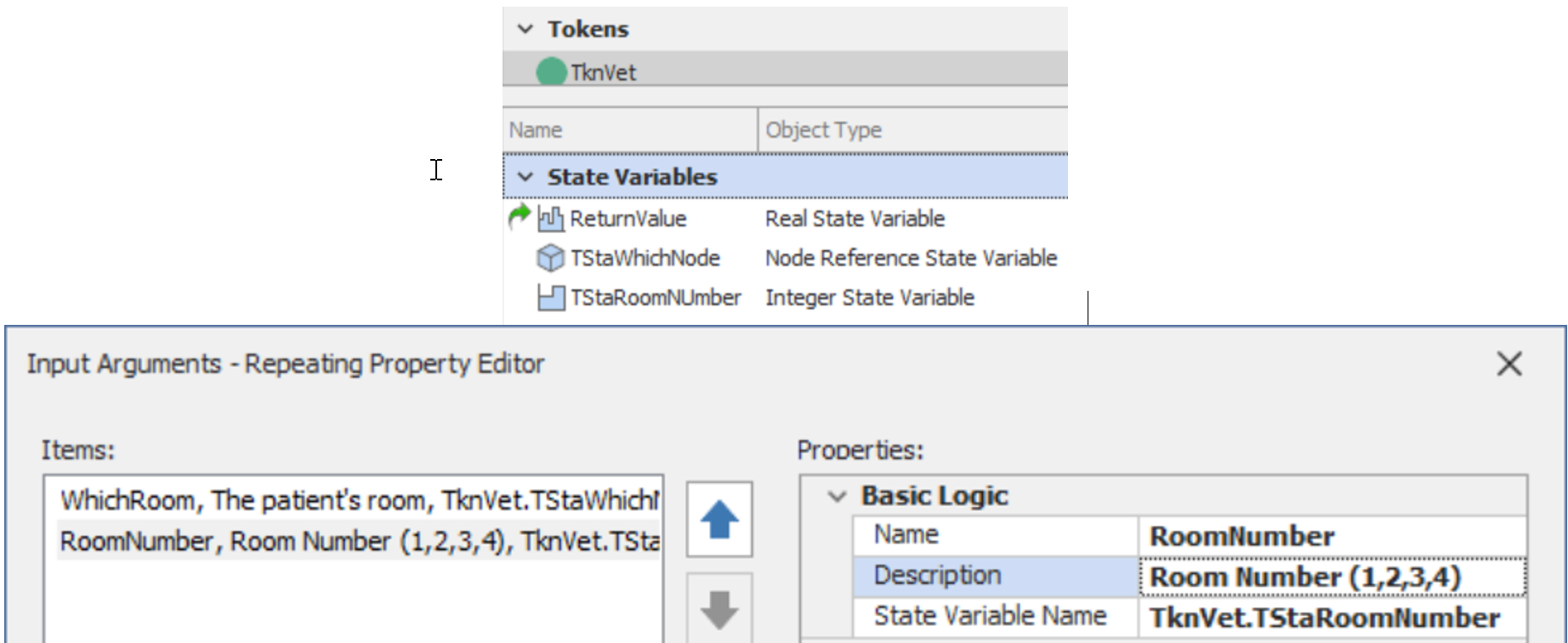
Figure 14.21: Adding a new Input Argument to the Tokenized SeizeVet Process
14.4.9 Next, add an Assign step to SrvRoom2_BeforeProcessing before the Seize step that assigns a new value of “1” to the ModelEntity.Picture state variable.
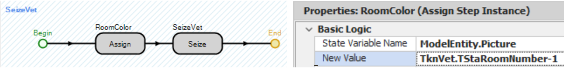
Figure 14.22: Changing the Patient Color based on the Room
14.4.10 Modify the Before_Processing for each of the rooms and specify “1”, “2”, “3”, and “4” for the Room Number input argument for SrvRoom1, SrvRoom2, SrvRoom3, and SrvRoom4 respectively.
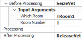
Figure 14.23: Passing the Room Number for SrvRoom1
14.4.12 The patient entities are changing color based on the room they enter. The paperwork entity now needs to reflect the color of the patient that created it. Process steps like Create and Search cause new tokens to be created that are now associated with either the new entity created in the Create step or the objects found in the Search step. Therefore, state variables associated with the original token’s object (i.e., the ModelEntity.Picture) are not accessible to the new objects. One common approach to copy states from one entity to another is to create a global (i.e., Model) state variable that is accessible by all objects of the model.215 Add a newInteger Discrete State variable named GStaPictureID from the Definitions tab.
14.4.13 Next, add an Assign step before the Create step in the ReleaseVet process that assigns the GStaPictureID to the ModelEntity.Picture of the patient entity that is creating the paper work. Then insert another Assign step before the Transfer which is associated with the newly created paper work entity that assigns the model state variable GStaPictureID to the ModelEntity.Picture state variable as seen inFigure 14.24.
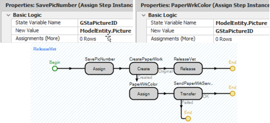
Figure 14.24: Copying the Value from One ModelEntity to another ModelEntity
14.5 Zero-Time Events
The issue seems to be that the vet essentially processes the previous patient’s seizure even though the paperwork has a higher priority. A discrete-event simulation executes the simulation through an event calendar that is ordered by the time of the event. Zero-time events are events that occur at the exact same time.216 The Seize step for the paperwork entity happens simultaneously with the Release step for the room. If the release step occurs before the Seize step occurs, the vet may serve a patient in a different room. Ordering of zero-time events can become critical in the execution of the model, and the modeler won’t know which is done first without some detective work.
A great tool for understanding what is happening during your simulation is through the use of the “Model Trace.” The “Model Trace,” initiated from the “Run” tab, is the most complete description of what is happening. However, in this case, you want to trace the behavior of a process. You do this by selecting the step in the Processes tab and clicking the breakpoint button in the Process Tables ribbon, which will place the breakpoint symbol adjacent to the step217. Now, in the “Facility” tab, select the Model Trace button, which displays the trace in its own window.
14.5.3 After the simulation “breaks”, click the Step button a couple of times. (You can recognize the break because the line colored red describes the breakpoint.) When you click the Step button, a series of actions are shown, colored in yellow, representing that simulation step. You may need to scroll back up to see the breakpoint statement.
###Figure 14.25218 is a printout of all the events that have occurred around the breakpoint.
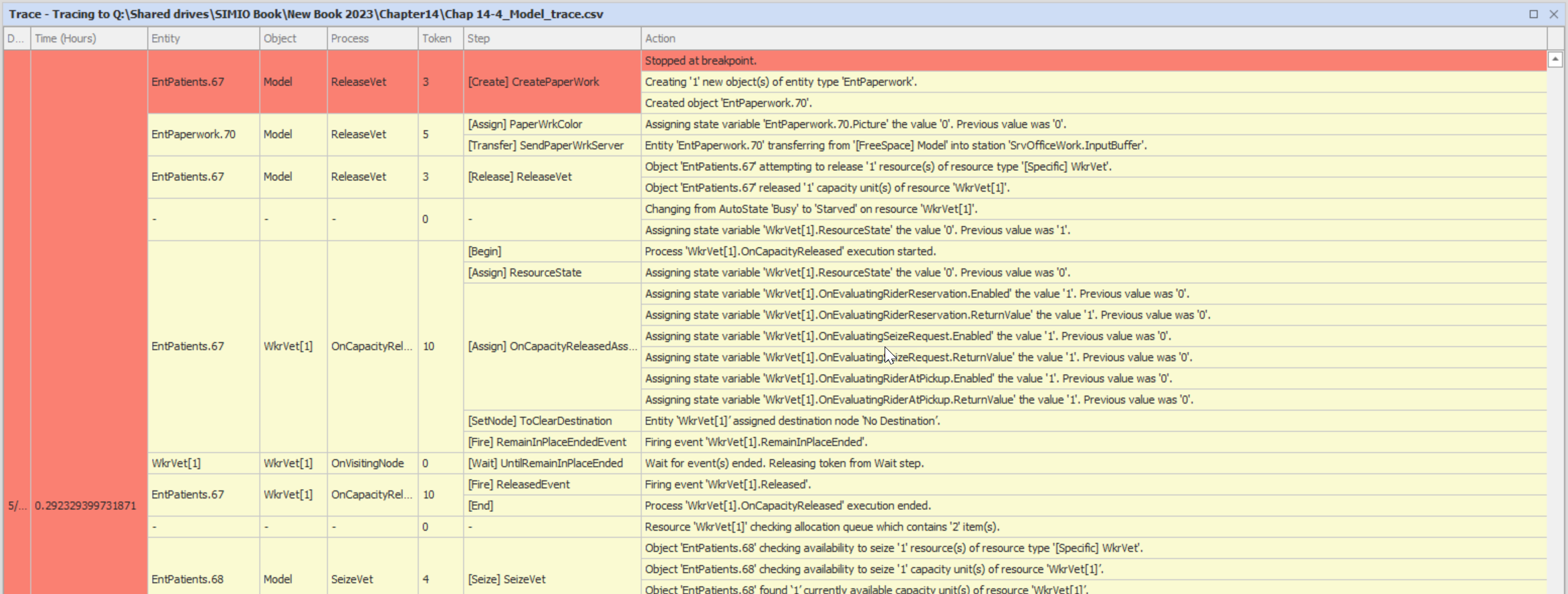
Figure 14.25: Sample Trace showing the Ordering of the Zero-Time Events
14.5.4 Now, you should read down the trace, noting the entity, the object, the step, and the action. Here, we see that the paperwork entity is created (EntPaperwork.70), the picture variable is assigned the value of 0, and that entity is transferred to the “SrvOffice.InputBuffer.” Next, the patient entity (Entpatients.67) releases one unit of capacity of the vet. Scrolling down through the other zero-time events, you will see that the vet will then respond to a request from another room first because the paperwork entity does not request one unit of capacity from the vet until near the very end of the current time.219 All this is done at the same simulation time, but the ordering is important.
14.5.5 We need the release to happen after the Seize step, which implies that the concurrent time events need to be reordered. To accomplish a reordering of events, you can insert a Delay step before the release of the vet (seeFigure 14.26) that will delay the current token (representing the patient) a very small amount of time by specifying the delay time to be Math.Epsilon.220 Also, change the Token Wait Action of the Create step to WaitUntilNewTokenProcessingCompleted.
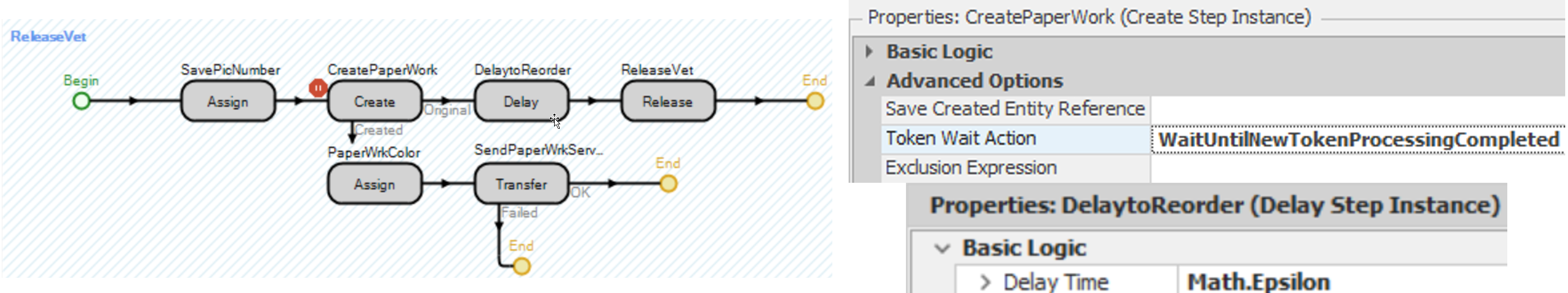
Figure 14.26: Reordering Zero Time Events by Delaying an Epsilon Amount of Time
14.5.6 Save and run the model again, performing a few “Steps” after the breakpoint, which yields the trace inFigure 14.27. As you can see, the delay causes all the steps following it to become late priority events, meaning they will be placed at the end of the current time. This allows the paperwork to seize the vet first, which then allows the vet to select it based on its priority.
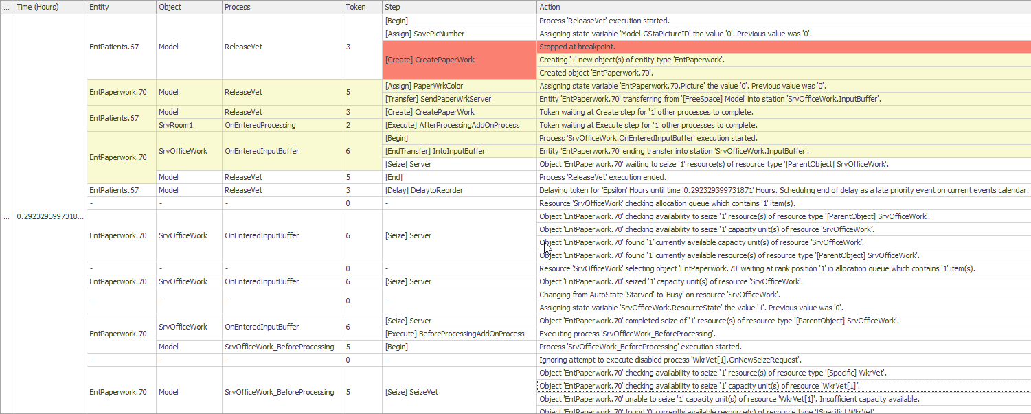
Figure 14.27: Reordered zero-time events
14.6 Handling Multiple Vets
In the previous section, there were multiple vets that could process patients. Like other dynamic objectsModelEntities and Vehicles, multipleWorkers can be created at the start of the simulation or during the simulation run. Let’s add two more vets to help in the clinic.
14.6.1 Select the WkrVet and change the Initial Number in System property to “3” under the Population category.
14.6.2 Change the SrvOffice capacity to “Infinity” so each of the vets can service their own paperwork.
14.6.5 Transition back to the Model and insert a new model Discrete Integer State variable named GStaModelResID. This variable will be used to pass the resource ID that was seized by the patient to the paperwork entity in a similar fashion as the picture number that was passed.
14.6.6 Next, we need to set the global (i.e., model) variable (GStaModelResID) with the vet the current patient has seized before we create the paperwork entity and then set the paperwork entity’s EStaResourceID variable the value of the model variable. Inside the ReleaseVet, modify the first Assign step (i.e. GStaPictureID) to include another assignment which sets GStaModelResID a value of ModelEntity.SeizedResources.LastItem.ID.222 Then, modify the second Assign step on the “Created” path (i.e., PaperWorkColor) to set the ModelEntity.EStaResourceID variable a value of GStaModelResID as seen inFigure 14.28.

Figure 14.28: Passing Seized Resource ID to the Newly Created PaperWork Entity
14.6.7 Modify the Seize step in the SrvOffice_BeforeProcessing process to request a particular Vet that needs to perform the paperwork based on the state variable ModelEntity.EStaResourceID. Under the Advanced Options, specify the Selection Condition property to be Candidate.Worker.ID == ModelEntity.EStaResourceID as seen inFigure 14.29. Recall the Candidate is a wild card designator and will match all the WkrVets that are currently in the system. The Selection Condition property has to evaluate to “True” for the WkrVet to be in the pool of potential ones to be seized and in this example all WkrVets will be eliminated for consideration except the one whose ID matches the EStaResourceID value.
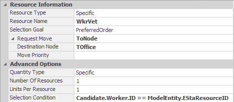
Figure 14.29: Selecting Only the Correct Vet for the Paper Work
14.7 Commentary
- Dynamic resources offer considerable modeling capability. In this chapter, we utilized processes to seize and release the work stating it offers the most control over the process. However, in this case we could have utilized secondary resources to accomplish the same task of the two processes used to seize and release the vet. Figure 14.30 displays For Processing property Resources for Processing repeat group values under the Secondary Resources section for the SrvRoom1 that would seize the vet and wait for it to arrive before processing.
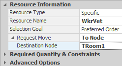
Figure 14.30: Specifying the Seizing and Release of the Vet Using Secondary Resources
- We fixed the zero-time event by reordering the concurrent events using a delay step. Another solution would have been to seize the vet before transferring, as seen inFigure 14.31. The “Original” token waits until the “Created” token reaches the end of the current process. Therefore, the seize will happen before the release in the zero-time events.
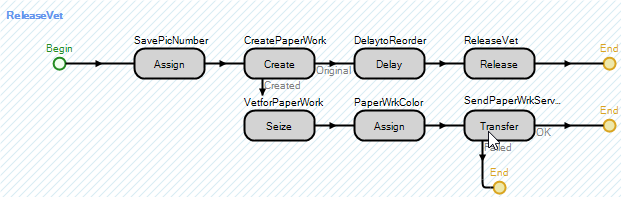
Figure 14.31: Seizing the Vet before Transferring the Paperwork
- Decision-making objects offer a number of modeling options especially as they relate to resources, transporters, and workers. Because there is so much flexibility, it can confound the choices. However, by working with these objects, you begin to develop some modeling patterns that seem more appropriate than others.
- While it is our intent to use as many modeling approaches as we can, it will still be necessary for you to supplement our efforts. Features such as the breakpoints, trace, and watch can be extremely helpful in learning how SIMIO is behaving. It’s hard to modify a behavior unless you understand the existing behavior.
- Unfortunately, the behavior of workers and vehicles is quite complex. Because of the complex behavior, these objects could be called ” heavyweight.” In some object-oriented designs, heavyweight objects are composed of “lightweight” objects which are less complex. However, that is not the case with SIMIO, so we will continue to investigate and employ the complexity of these objects.
To be more efficient, create one room named SrvRoom with all the correct properties and then copy it three times, changing the name of the original one to SrvRoom4 accordingly.↩︎
From the Drawing tab, insert a Polyline to represent the walls. You should do separate lines for the outside walls so you can add different textures. Change the width of the outside wall lines under the Drawing tab to 0.25 meters and a height of 3.5 meters.↩︎
Connectors are used to connect the outputs of the rooms to the BasicNodes while paths with appropriate logical lengths of 15 meters are used to connect the BasicNodes from rooms two to one, three to four, one to the waiting room node, and three to the waiting room.↩︎
When you access the AssociatedStation functions for an external node, you are given access to the actual station and all of its properties, states, and functions.↩︎
The capacity of the Server (i.e., the Processing Station) is not included unless the input buffer capacity is zero. Then, all the functions report values associated with the Processing Station instead of the InputBuffer Station. Note that an infinite capacity is represented by the maximum integer value of 2147483647.↩︎
The AssociatedStation.Contents for the input buffer does not include the entities that are currently being processed by the Server or in the OutputBuffer Station. The AssociatedStationLoad does not include those in the OutputBuffer Station↩︎
You can select all four rooms and then set the Input Buffer to “0” under the Buffer Capacities properties at once. Here the spreadsheet view is also useful.↩︎
Again we will utilize the option that gives you the most control (i.e., processes). However, in this case Secondary Resources could be used and is demonstrated in the commentary.↩︎
You can remove an add-on process trigger either by using the right click reset menu option or selecting the trigger name and then deleting it.↩︎
Select all the paths and specify the direction and the logical length at one time or Object Property Spreadsheet.↩︎
This is for animation purposes since the Vets would disappear when they arrive at their destination and begin service.↩︎
Another option is to insert a new worker named VetB. Then a resource list would have to be created to allow entities to seize one from the pool of resources. This modeling approach may be necessary if the two staff members can service different types of patients, different processing times, have a different ordering or work schedule, etc.↩︎
The Dynamic Selection Rule is used here only to illustrate its use and is strictly not necessary. The only case when the dynamic selection rule is needed is when the Value may be changed while the entity is waiting, such as when a due date is reached.↩︎
Note this time we are sending the entity directly to the input buffer station rather than the Input node at the Server which will force the paper work to seize the vet without having to be transferred from the input node to the input station.↩︎
Instead of creating a new Object in the Create step, a copy of the associated object could be created which would inherit all the properties and states of the creating object. This approach could have been used in this case but the statistics associated with EntPatients could not be used since this would include the paper work entities as well since they would be the same entity type. Also we could have created a tokenized ReleaseVet process that would take in the room number and therefore would know the color that needed to be set.↩︎
There are dozens of events that can occur that same time and can become an issue especially when dealing with allocations of resources, workers, and vehicles.↩︎
You can also right-click the step and select the “breakpoint”.↩︎
The trace is automatically saved to a CSV file as the model is running and can be imported into Excel for further analysis and manipulation if necessary. You can also filter each column by selecting a row and the right clicking on the column heading.↩︎
It may be necessary to click the Step button again to get the next set of zero time events owing to the number of events that occur.↩︎
Math.Epsilon represents the smallest real value number greater than zero. Delay steps will actually interpret the number as zero, but it forces the event to be put at the end of the current event calendar. If the delay time is specified as zero, SIMIO will not place the event on the calendar thus not changing the order at all. In the commentary, another solution to the ordering is presented.↩︎
All objects created in the simulation receive a unique identifier (ID which can be used. For example EntPatients.61 is a patient whose ID is 61.↩︎
The vet will be the last resource seized since the patient had to first seize the server before it was allowed to go into processing and then request the vet. See Table 13.2 for more information on the SeizedResources property of the entity.↩︎