Simulation Modeling with Simio - 6th Edition
Chapter
22
More Subclassing: Process Planning/Project Management
22.1 Process Planning
A new product (called Product 3) is being introduced. One unit of Product 3 is produced by assembling one unit of Product 1 and one unit of Product 2. Before production begins on either Product 1 or Product 2, raw materials must be purchased, and workers must be trained. Before Products 1 and 2 can be assembled into Product 3, the finished Product 2 must be inspected. Table 22.1 gives the list of activities and their predecessors and the average duration of each activity.
| Activity | Predecessors | Duration (days) |
|---|---|---|
| A = train workers | – | 6 |
| B = purchase raw materials | – | 9 |
| C = produce Product 1 | A, B | 8 |
| D = produce Product 2 | A, B | 7 |
| E = test Product 2 | D | 10 |
| F = assemble Products 1 and 2 | C, E | 12 |
The typical project management diagram for example can be seen in Figure 22.1.

Figure 22.1: Project Planning Example
Clearly, the project will take an average of 38 days, and activities B, D, E, and F are critical (“on the critical path”), meaning if any of these increase, then the time to completion will increase. However, in reality, activity completion times are uncertain (random), and different activities may become critical. So, we can’t rely on deterministic values for the activity times; instead, we need to represent the times with random variables.
Also, activities might share resources to complete the task. Therefore, the goal will be to determine the critical path and the probability that a path will be on the critical path. Some activity statistics of interest are shown in Table 22.2.
| Statistic | Description |
|---|---|
| Earliest Finish | The time the current task finishes (i.e., entity leaves the path). |
| Latest Finish | The time the current task could finish without changing the critical path or causing the successive tasks to start later. |
| Slack | The time difference between the Earliest Finish and the Latest Finish |
| Percent CP | The percentage of the time the current path is on the critical path. |
Earlier chapters have demonstrated the ability to specialize/subclass existing objects, which allows additional characteristics and behaviors to be added or existing ones to be modified, but none have specialized one of the link objects (i.e., Paths or TimePaths). We will model the project management problem using the TimePaths to consume time. We will also use one replication to represent a single project completion, so multiple replications will be used to characterize the project statistically.
22.2 Creating a Specialized TimePath to Handle Activities
The ability to create new objects is one of the advantages of SIMIO, and the TimePath link is an attractive object to use for the activity time since the entities can be seen visually moving along the paths. The paths represent the important objects (i.e., critical path determination). Each path needs to keep track of its own statistics (i.e., Earliest Finish, Slack, Percent CP, etc.). The path also needs to know when an entity reaches the end of the path and restrict only one entity from traveling on each path. This encapsulation of the time path gives the object the “intelligence” to calculate the statistics automatically and allows us to utilize it for many different project management problems.
22.2.1 Create a new model, subclass the TimePath, and change the Model Name property to PrjTimePath314.
22.2.3 To keep track of critical path calculations, add three Tally statistics named TallyStatEarliestFinish, TallyStatSlack, and TallyStatPercentCP via the Definitions→Elements section.
- Change the “Category” property to “Critical Path” for all three Tally statistics under the “Results Classification.
- Change the Data Item property to “Earliest Finish,” “Slack,” and “Percent CP” for the appropriate statistic.
- Also, for the TallyStatEarliestFinish and TallyStatSlack, set the Unit Type to “Time.”
22.2.4 Recall only one project will be completed for each replication. In order to model a “junction” from which multiple activities start, the paths should not allow more than one traveler, and travel should be in one direction only. From the Definitions→Properties, click on the down arrow to reveal the inherited properties.
- Select the IntialTravelerCapacity property and change the Default Value from Infinity to one and the Visible property to “False” so a user cannot change it, and it will automatically be set.
- Select the InitialDesiredDirection property and change the Default Value to forward and the Visible property to “False” so a user cannot change it, and it will automatically be set (See Figure 22.2).
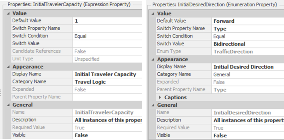
Figure 22.2: Setting the Default Values of the Travel Capacity and Desired Direction
22.2.5 The TimePath defines seven processes that determine the behavior of the link, as seen in Table 22.3.
| Process | Description |
|---|---|
| OnEntered | Process runs when the leading edge of an Entity, Worker, or Transporter reaches the beginning of the TimePath. |
| OnExited | Process runs when the trailing edge of an Entity, Worker, or Transporter leaves the TimePath. |
| OnReachedEnd | Process runs when the leading edge of an Entity, Worker, or Transporter reaches the end of the TimePath. |
| OnRunEnding | Process runs once at the end of the simulation. |
| OnRunInitialized | Process runs once at the beginning of the simulation. |
| OnTrailingEdgeEntered | Process runs when the trailing edge of an Entity, Worker, or Transporter enters the path. |
22.2.6 Once the project Entity reaches the end of the path, the activity is finished, and the earliest finish time can be calculated. Override the “OnReachedEnd” process as seen in Figure 22.3, to perform the calculation.
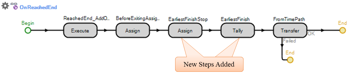
Figure 22.3: Calculating Earliest Finish and Shutting Down Path
- Insert an Assign step that will set the DesiredDirection to Enum.TrafficDirection.None will shut down the path and not allow any more entities to travel this path. Also, set the StaEarliestFinish state variable to the current time (Run.TimeNow. Refer to Figure 22.4.
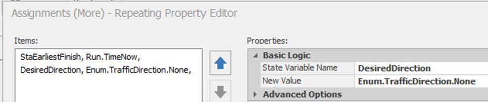
Figure 22.4: Shut down the Path and Set the Earliest Finish
- Insert a Tally step to add one observation of the TallyEarliestFinish statistic. as seen in Figure 22.5.
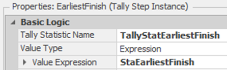
Figure 22.5: Add an Observation of the Earliest Finish Statistic
22.3 Creating a Junction Object to Handle Precedent Constraints
In the previous section, we modeled the project activities as specialized TimePaths, automatically calculating all the statistics. However, they cannot enforce the precedence constraints or start-up activities nor determine when the latest finish happens. The precedence constraints have to be enforced by the junctions, which also initiate the next set of activities. Therefore, the junction has to wait until all the preceding activities have finished before starting all of the succeeding activities at the same time. Also, the junctions determine the latest finish of all the preceding activities based on the time the last of the preceding activities finishes.
22.3.1 None of the standard objects can model this circumstance easily, and most standard objects are too complicated to modify for this purpose. A new object similar to the Delay object of Chapter 20 will be created. From the “Project Home” tab, insert a new “Fixed Class Model” named Junction, which will be used to model the junctions.
22.3.2 We need our junction to act as a start node and an end node, as well as intermediate junctions within the project network. Start nodes will start activities at the start of the project, while the end nodes will terminate all activities at the end of the project.
- Insert a new String List from the Definitions→List→Create section named ListJunctionType with three entries, as shown in Figure 22.6. This will allow the user to choose the Junction Type.

Figure 22.6: Defining Different List Types
- Insert a new standard “List Property” named JunctionType, which allows the modeler to specify the junction type with “Junction” as the default type and place it in the “Project Management” category, as seen in Figure 22.7.315
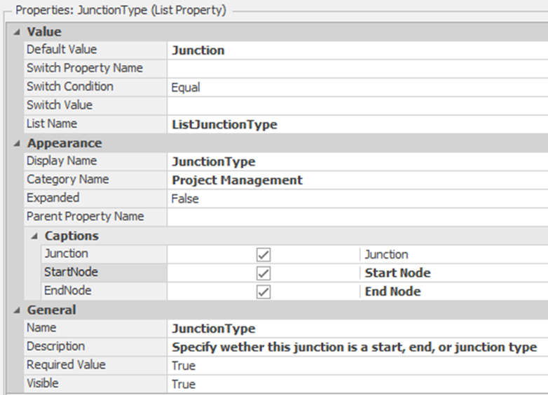
Figure 22.7: Specifying the List JunctionType Property
22.3.3 If the Junction object is a “Start Node,” it will need to create entities to be sent out into the project network like the standard Source. From the Definitions→Properties→Add→Object Reference¸ add an Entity property named EntityType, making sure to place it into the “Project Management” category created in the step before. Also, you only want the property displayed if the JunctionType property is set to “StartNode.” See Figure 22.8.

Figure 22.8: Specifying the Start Node
22.3.4 Each junction needs to know the number of precedent activities to wait on and the number of successive activities to start. Insert two new Discrete integer State properties named StaPredecessors and StaSuccessors, which will be set at the beginning of the simulation run.316
22.3.5 Insert a Discrete integer State variable named StaActivitiesCompleted, which will keep track of the number of activities that have been completed, and a Discrete Real State variable named StaLatestFinish, which will record when the time the last activity has been completed.
22.3.6 As was done in Chapter 20, the Delay object, the incoming entities need a location where actions can occur. From the Definitions→Elements, insert a new Station named Project with all the default values.
22.3.7 Next, let’s define the external view seen by the user of the Junction object.
- From the Definitions→External→Drawing section, use a Polygon shape to draw a red diamond, as seen in Figure 22.9.
- Insert an External Node that is a BasicNode on the left edge of the red diamond that will accept incoming activities and automatically send them to the Project Station.
- Next create the output of activities by inserting an External Node that is a TransferNode on the right edge of the red diamond that will route successor activities.
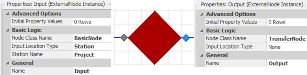
Figure 22.9: External View of the Junction Object Along with Input and Output Nodes
Now that we have defined the external view and activities (i.e., entities) that can flow in and out of our object, we need to add the process logic to handle the precedence and the starting of the activities as well as determining the number of predecessors and successors.
22.3.8 From the “Process” tab, select the OnRunInitialized process from the Select Process dropdown. Insert an Assign step that will set the number of predecessors (i.e., StaPredecessors to Input.InboundLinks.NumberItems) and the number of successors (i.e., StaSuccessors to Output.OutboundLinks.NumberItems) as shown in Figure 22.10.
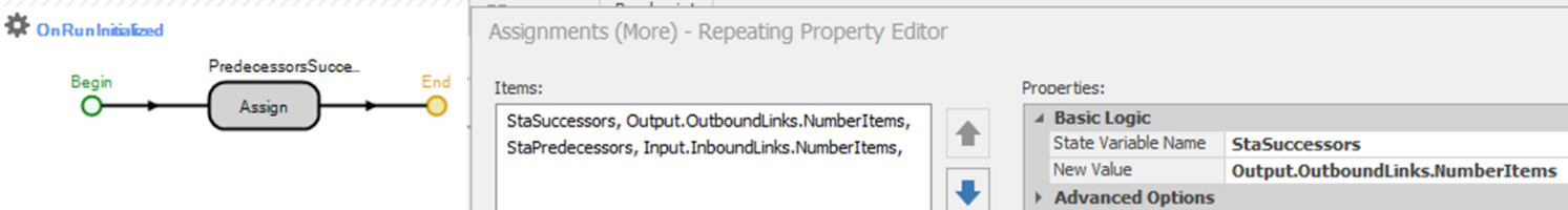
Figure 22.10: Initializing the Number of Successors and Predecessors
22.3.9 Create a new process named “OnEnteringProject” that will execute every time an activity (i.e., Entity) enters the Project station by specifying the Triggering Event to be “Project.Entered,” as seen in Figure 22.11. The process needs to update the number of activities finished. If the number of activities equals the number of predecessors, it will create the number of successors and send them out to the network. Otherwise, activities still need to be completed, and we will destroy the current activity entity.
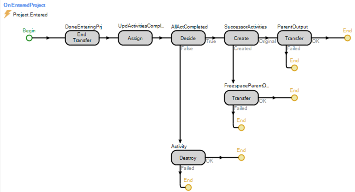
Figure 22.11: Process to Handle Activities that Enter the Junction
- As always, you first need to end the transfer of the entity object into the station by inserting an End Transfer step.
- Next, update the number of activities that have been completed by one, as shown in Figure 22.12.
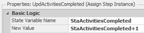
Figure 22.12: Updating the Number of Activities by One
- Now, decide if all the precedent activities have been completed (i.e., StaActivitiesCompleted == StaPredecessors) as seen in Figure 22.13.
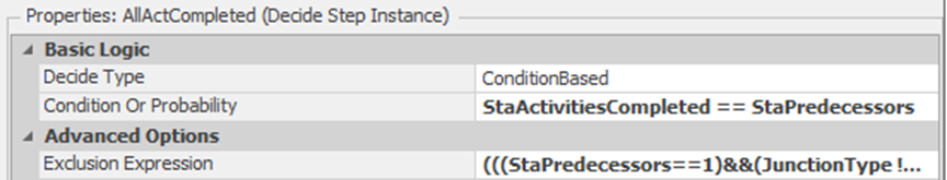
Figure 22.13: Deciding if All Preceding Activities are Complete
- Note the use of the Exclusion Expression property, which can be used at the start of the simulation to determine if this step is necessary.317 If the Junction is a “StartNode” or only has one preceding activity, then the next set of activities can be automatically started (it will be set to one), or if this is an “EndNode,” then these entities can be automatically destroyed (i.e., set to two). If you know at the start of the simulation, skipping steps can greatly speed up the simulation since it does not need to be evaluated. Set the Exclusion property to the following.
(((StaPredecessors==1)&&(JunctionType.ListJunctionType.EndNode)) || (JunctionType == List.ListJunctionType.StartNode)) + 2*(JunctionType == List.ListJunctionType.EndNode)
- If the total number of preceding activities has not been completed (i.e., some activities are still waiting to be completed), then insert a Destroy step to kill the current activity entity.
- If this activity is the last one to complete or the junction is a “Start Node,” then we need to start the next set of successor activities. Insert a Create step that will create copies of the current Entity (i.e., set the Create Type property to “CopyAssociatedObject”). The Number of Objects will be set to StaSuccessors-1 since one activity Entity is already present. Note the use of the Exclusion Expression property to skip this step if there is only one successor, as seen in Figure 22.14.
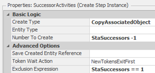
Figure 22.14: Creating the Successor Activities
- Using Transfer steps, the original activity Entity needs to be sent from the “Current Station” to the “ParentExternalNode” Output, while the newly created activity entities need to be sent from”Free Space” to the same ParentExternalNode Output as seen in Figure 22.15.
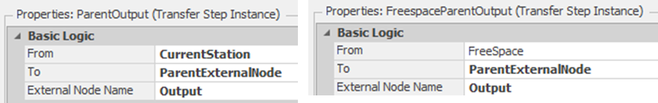
Figure 22.15: Sending Successor Activities Out to the Network
22.3.10 If the Junction is a “Start Node,” then it must automatically create the start activity to start this branch of the network. Therefore, the “OnRunInitialized” process which is executed for each object at the beginning of the simulation, will be used to handle this logic. Select the “OnRunInitialized” and add a Create and Transfer steps after the Assign sets the number of predecessors and successors, as shown if Figure 22.16.
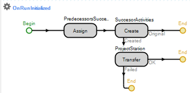
Figure 22.16: OnRunInitialized Process to Start Activities
- Insert a Create step that will produce one new object of EntityType property. Again, right-click on the Object Instance Name property and select the referenced property. Again, note the use of the Exclusion Expression property to skip this step if it is not a “Start Node.” Refer to Figure 22.17.
- If it is a start node and an activity has been created, then insert a Transfer step to move it from “FreeSpace” to the Project Station.318 This will then run the “OnEnteringProject” process, which will produce the correct number of successors without repeating the code, as seen in Figure 22.17.
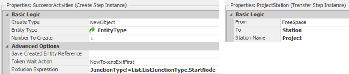
Figure 22.17: Create and Transfer Steps for the OnRunInitialized Process
22.4 Creating Small Network to Test the New Object
At this point, our junction object seems to be set up to handle the precedence constraints and start new activities. Go back to the original model and create a very simple network to test this ability. At this point, we will not have to worry about naming the objects.
22.4.1 Insert a new Model Entity named EntActivities and four Junction objects, leaving their names as the default. Place them in the configuration as seen in Figure 22.18.
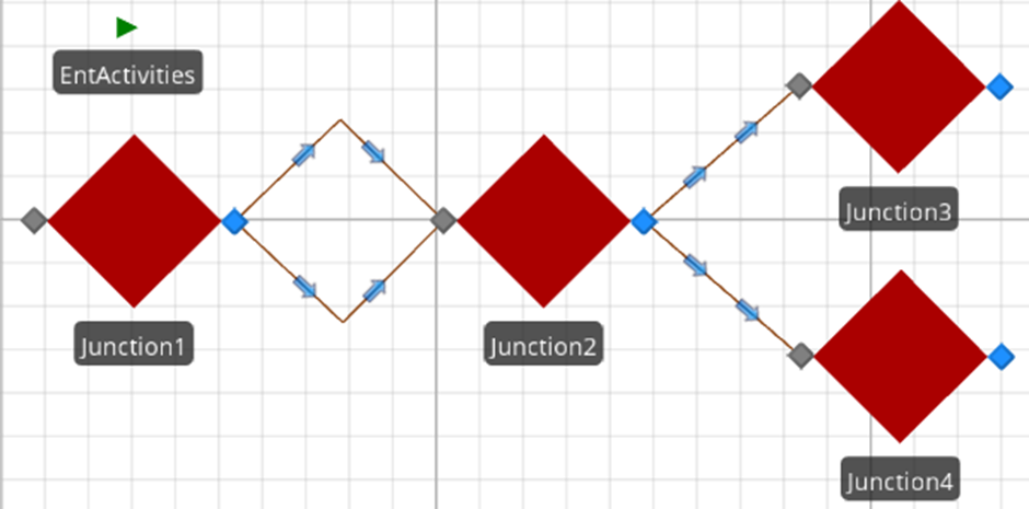
Figure 22.18: Simple Network to Test the Junction Object
22.4.2 Connect Junction1 to Junction2 via two PrjTimePaths with one path taking one day and the other one taking two days and then connect Junction2 to Junction3 and Junction4 via one day PrjTimePaths.
22.4.3 Set Junction1 to be a “Start Node” while Junction2 should be just a “Junction,” as seen in Figure 22.19. Set Junction3 and Junction4 to each be an “End Node.” Set the model to run for four days.
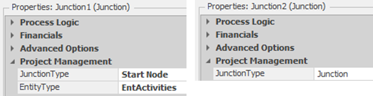
Figure 22.19: Setting up the Start Junction and the Secondary Junction
22.4.4 Save and run the model, observing what happens.
22.4.5 It looks like only one was created when actually both were placed on the same path. Click on the Output node of Junction2 and change the Outbound Link Preference from “Any” to “Available,” which is used to select the next link. In this case, we only want to select from the currently available ones.
22.4.7 At this point, the user will have to change the default property from “Any” to “Available” every time which is not acceptable since they may forget. Therefore, we will automatically set it for the modeler by specializing the TransferNode object. Subclass the Transfernode object and name it PrjTransferNode.
22.4.9 Return back to the Junction object and select the external Output node in the Definitions→External section. Change the Node Class property from the TransferObject to the new PrjTransferNode, as seen in Figure 22.20.
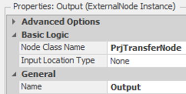
Figure 22.20: Changing the Output node to PrjTransferNode
22.5 Building the Example Network
Let’s build the simple example from the beginning section.
22.5.1 From Project Home, create a new Fixed Model and insert Junctions and a ModelEntity using the names as shown in Figure 22.21.

Figure 22.21: Example Project Management Model
22.5.2 Use PrjTimePaths to represent each of the activities by connecting two Junctions together. Table 22.4 should be utilized to specify the name of each path and set the Travel Time and Units properties.
| From | To | Name | Travel Time | Units |
|---|---|---|---|---|
| Junction 1 | Junction 2 | A | Random.Pert(5,6,10) | Days |
| Junction 1 | Junction 2 | B | Random.Pert(6,9,9) | Days |
| Junction 3 | Junction 4 | C | Random.Pert(6,8,16) | Days |
| Junction 2 | Junction 3 | D | Random.Pert(4,5,7) | Days |
| Junction 2 | Junction 4 | E | Random.Pert(6,7,10) | Days |
| Junction 4 | Junction 5 | F | Random.Pert(8,12,16) | Days |
22.5.3 Next, use the values in Figure 22.22 to specify each of the five junctions’ Project Management properties to ensure the precedent constraints are satisfied and the number of successor activities are started.
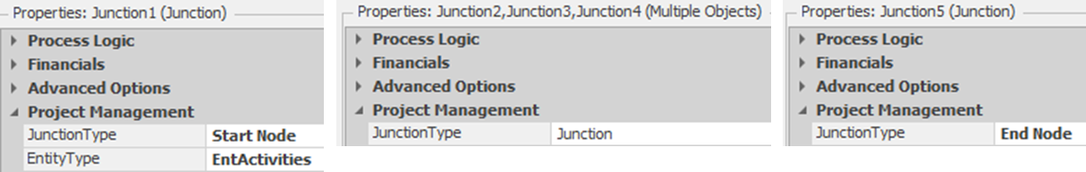
Figure 22.22: Properties of the Five Junctions
22.5.4 Save and run the model, and make sure the run length is “Unspecified,” which will stop the simulation when no more entities are in the system.
22.5.5 Remember, we decided to model one project completion with one replication. Therefore, insert a new experiment that will replicate the project management network 1000 times.
22.5.6 Run the experiment and look at the results under the “Pivot Grid tab. Change the unit settings from time to days.
22.5.7 Filter the “Category” column by clicking on the funnel in the right-hand corner (see Figure 22.23) and, select only the “Critical Path” statistics, and then filter the “Statistic” column to include the “Average” since we only have one observation per replication. Figure 22.24 shows the reduced statistics where the project will take between 27 and 38 days, with the average taking 33 days plus or minus 1.8 days319.
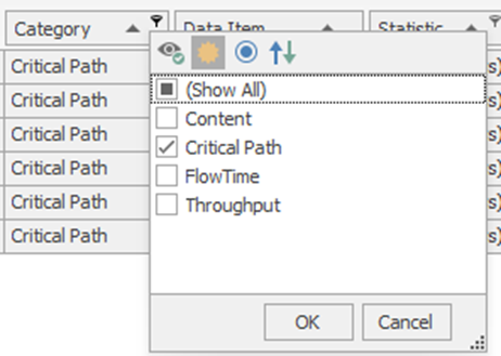
Figure 22.23: Filter the Category only to Include Critical Path Statistics

Figure 22.24: Earliest Finish Statistics for 1000 Replications
22.6 Adding the Slack and Percent of Time on Critical Path Calculations
At this point, we can determine the Earliest Finish (EF) time of all the paths and the total time to complete the project, but it is difficult to determine what paths constitute the critical path since path times are random. However, the slack time for each path and the percentage of time this path is on the critical path can assist the project manager. The Earliest Finish (EF) time can be calculated without any other information from other objects. However, the computation of the Latest Finish (LF) requires knowing the slack and the number of times the path is on the critical path.
The Latest Finish time is only known at the junctions and is determined when the last activity finishes. When two SIMIO objects need to communicate with one another, there are two ways to approach this communication. In the first approach shown in Figure 22.25, the Junctions need to know the PrjTimePaths that are connected to them. The PrjTimePaths will monitor a state variable within their object that is set to one by the Junction when the last activity finishes. In the second approach, the PrjTimePaths need to know the Junctions to which they are connected, and they will monitor a state variable inside the Junction object. We will illustrate the first approach in this section, where the monitoring state variable resides inside the object that is monitoring.
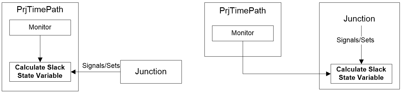
Figure 22.25: Approaches to Signaling from One Object to Another
22.6.1 Save the current model as a Chapter 23-6.spfx because we will need to return to the previous section model to create the second approach, so we need to ensure it is saved before renaming it.
22.6.3 From the Defintions→Elements tab, insert a new Monitor named MonitorSlack, which will be used to calculate the slack calculation when the StaCalculateSlack state variable changes values to one, as seen in Figure 22.26.
- Set the Monitor Type to “DiscreteStateChange” and the State Variable Name to the StaCalculateSlack variable.
- Create a new Triggered Process Name to execute when the monitor event changes.
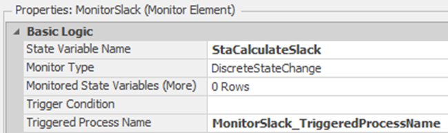
Figure 22.26: Setting up the Monitor to Calculate the Slack
22.6.4 Once the last activity has happened, the associated Junction will set the StaCalculateSlack state variable to one. Since this variable is being watched by the MonitorSlack, it will execute the “Triggered Process,” as seen in Figure 22.27.
- Insert a Tally step that will calculate the slack (LF-EF) where the latest finish is the current time and add either a zero or one to the TallyPercentCP to indicate whether or not the path is on the critical path or not. You need to select the Tallies (More) repeating group to set both statistics.
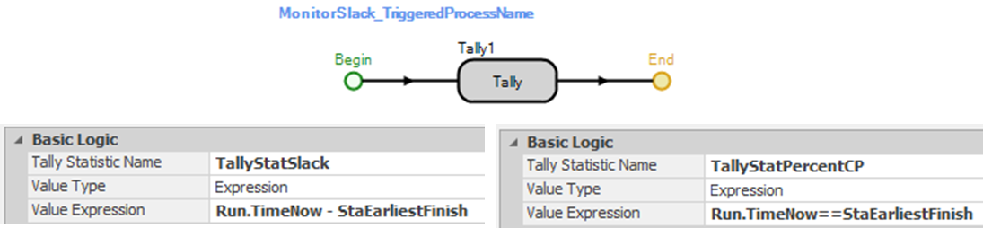
Figure 22.27: Calculating the Slack and Determining if it is on Critical Path
22.6.6 After the last precedent activity has finished (Junction object’s OnEnteringProject process), the StaCalculateSlack variable will need to be set to one for all the precedent paths. Insert a Search step that will be used to search for the correct activity paths right after the Decide step, as shown in Figure 22.28. Recall the search step, which returns a Token associated with the found object (i.e., PrjTimePath) and can then be used to set its own variable.
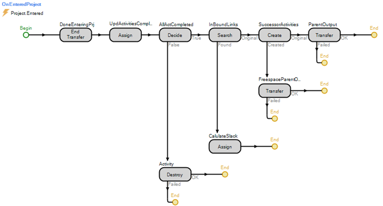
Figure 22.28: Setting the StaCalculateSlack Variable of the Paths When All Activities Have Finished
- Figure 22.29 shows the Search step that will search a “NodeInBoundLinks” where the Node Name property is set to Input, which is the parent input node. Note that this node will not be in the dropdown list but will need to be typed into the field. The Exclusion Expression (i.e., JunctionType == List.ListJunctionType.StartNode) specifies to skip this Search step if this Junction is a “StartNode” and does not need to notify in predecessor links.
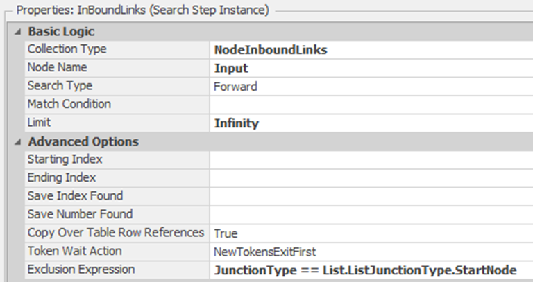
Figure 22.29: Searching for all Inbound Links
- Insert an Assign on the “Found” branch and specify with the values in Figure 22.30, which will set the PrjTimePath.StaCalculateSlack discrete variable to one.
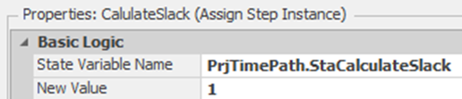
Figure 22.30: Setting the Calculate Slack Variable
22.6.7 Save and rerun the experiment.320
22.6.7.1 What percentage of the time is path A on the critical path?
_______________________________________________
22.6.8 Looking at the results, it is clear that the critical path is B D E F since these paths have the highest percentages of time on the critical path, as seen in Figure 22.31 for the Percent CP average.
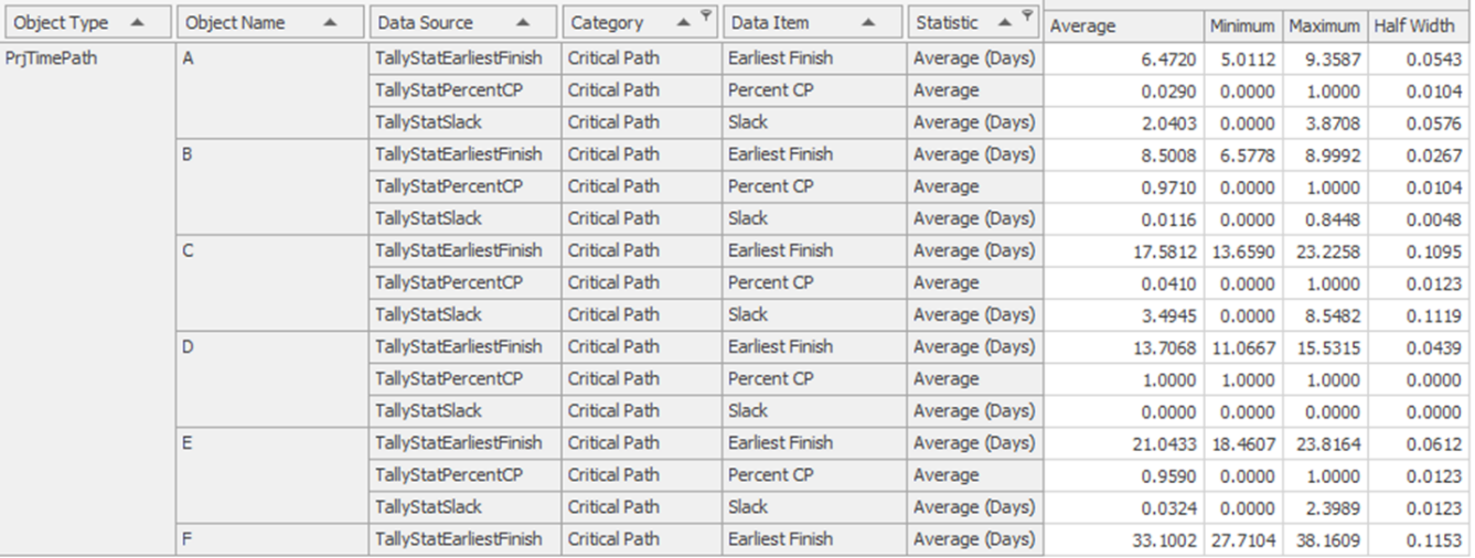
Figure 22.31: Results of the Critical Path Analysis
22.7 Adding Slack and Percent of Time on CP Calculations Second Approach
The previous section uses the Junction objects to signal (i.e., set the StaSlackVariable) the activity time paths of the Latest Finish. This section will take the alternative approach and let the PrjTimePath monitor a Junction state variable. This section demonstrates how an object can monitor the state variables of other objects, which can prove to be very useful in communicating among objects.
22.7.2 Remove the Search steps from the “OnEnteringProject” process and insert a new Assign step that assigns the current time (Run.TimeNow) to the StaLatestFinish state variable, as shown in Figure 22.32.
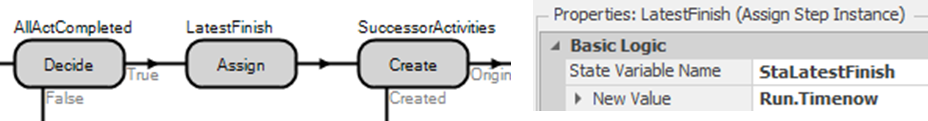
Figure 22.32: Setting the StaLatestFinish State Variable
22.7.4 From the Definitions→Properties→Add→Standard Property dropdown, insert a new State property named JunctionLF, which will allow the modeler to specify the Junction state variable to monitor. Change the Category Name to “Project Management” by specifying it, as shown in Figure 22.33.
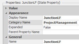
Figure 22.33: Create a State Variable Property
22.7.5 Modify the Monitor element MonitorSlack to monitor the new state reference property JunctionLF as seen in Figure 22.34.
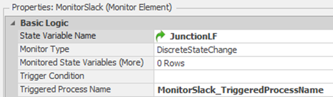
Figure 22.34: Using the Reference State Property to Monitor
22.7.6 Return to the model, and for each PrjTimePath, specify the appropriate Junction’s StaLatestFinish state variable.
- For example (see Figure 22.35), the Junction LF State Variable property should be set to Junction2.StaLatestFinish for both paths A and B.
- For paths C and E, D, and F it should be set to Junction4.StaLatestFinish, Junction3.StaLatestFinish, and Junction5.StaLatestFinish, respectively.
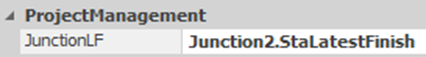
Figure 22.35: Specifying the State Variable
22.7.8 The problem was the last path did not calculate the latest finish statistics since it was heading to an “End” junction. Select the Junction object and then inside the OnEnteringProject process. Recall that all the entities were destroyed via the exclusion property of the Decide step (see Figure 22.13). Therefore, it is not sent to the Assign step. Therefore, remove the portion of the exclusion property associated with the end node: 2(JunctionType == List.ListJunctionType.EndNode). Then, add a Decide* step after the Assign to determine if the node is an EndNode and send the token to the Destroy step, as seen in Figure 22.36.
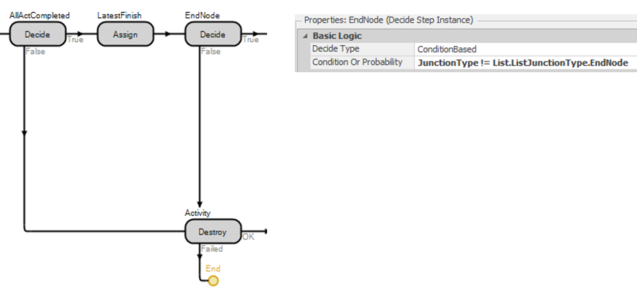
Figure 22.36: Modifying the Exclusion Expression and Adding a Decide Step
22.8 Error Checking to Make Sure Modeler Uses Junction Correctly
There are several assumptions the model has made. We are assuming the modeler will always connect up the junctions correctly using only the new PrjTimePath links. To eliminate this assumption, we will modify the OnRunInitialized to check for these issues, warn the modeler, and then end the simulation run, as seen in Figure 22.37.

Figure 22.37: Checking for Valid Links
22.8.1 Insert a new String State variable named StaWarningMessage to specify the particular message.
22.8.2 Insert a conditional-based Decide step to check to see if there are predecessor links connected to the Junction. If this is not a “Start Node,” the step will be skipped automatically as specified by the Exclusion Expression property. Insert another Decide step that will check to make sure the successor links have been defined if this is not an “End Node,” as seen in Figure 22.38.
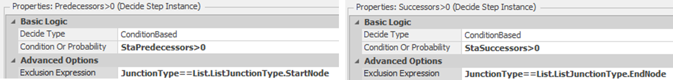
Figure 22.38: Checking to see if the Predecessors and Successors have been Defined
22.8.3 If the Predecessors>0 Decide steps fail (i.e., not start node but links are connected to the junction), insert an Assign step on the failed branch that will set the StaWarningMessage state variable to a string which states the Junction name as well as what to do to fix the issue.321
String.format(“{0} is Not a Start Node and there are no predecessors (i.e., Project Path links) defined”, Name)
22.8.4 Next, if the Successors>0 Decide steps fail, insert an Assign step on the failed branch that will set the StaWarningMessage state variable to a string that states the Junction name as well as what to do to fix the issue.
String.format(” {0} is Not an End Node and there are no successors (i.e., links) defined”,Name)
22.8.5 Connect both of the Assign steps to the same Notify step. The Notify step can either write a message in the Trace window or give a pop-up Warning to the user. We will use the StaWarningMessage as the Message Content property, as seen in Figure 22.39.
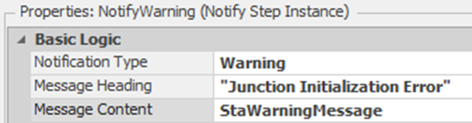
Figure 22.39: Sending a Warning to the User
22.8.6 Insert an End Run step that will terminate the simulation since the model has an error, and we don’t want to continue.
22.8.7 The first two Decide steps determined if no predecessor or successor links were defined. However, the user could connect the Junctions using normal Paths, Connectors, or TimePaths which is also an error. Insert two Search steps that will search both the inbound and outbound links as seen in Figure 22.40. The inbound search will be skipped if this is a “Start Node” while the outbound search will be skipped if the Junction is an “End Node” owing to the Exclusion Expression property.
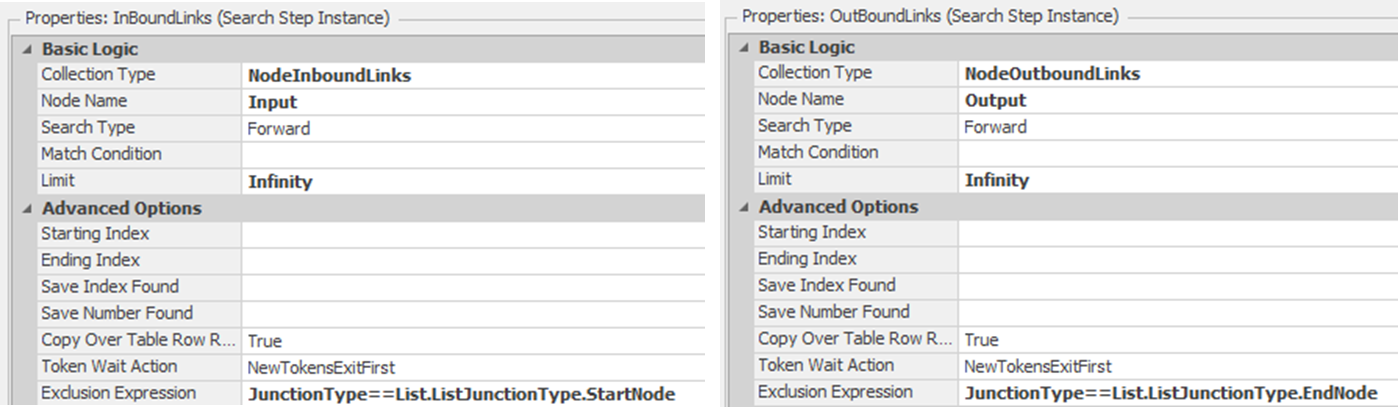
Figure 22.40: Searching to Make Sure the Predecessor and Successor Links are PrjTimePaths
22.8.8 When links are found, we must check to ensure they are PrjTimePath links only. Connect both “Found” branches to a conditional Decide step that checks to see if these are PrjTimePath using the Is keyword, which returns False if these objects are not project time paths. See Figure 22.41.
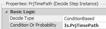
Figure 22.41: Checking to see if the Links are Project Time Paths
22.8.9 If any of the links are not project time paths, then set the warning message to tell the modeler which link is not a project time path that is connected to which Junction, as seen below.
String.format(“The successor or predecessor {0} connected to {1} is not a PrjTimePaths. Change the link to PrjTimePath”,Link.Name, Name)
22.8.11 Select the Facility window and test the new error checking by inserting another Junction into the model.
22.9 Commentary
- Sometimes, the activities within a project employ common resources. The resources can limit the number of simultaneous activities, and resource allocation and the timing of the allocation become limits on the project’s progress. Common resources can be incorporated directly into the PrjTimePaths. However, deciding which activities should be given priority for the resources can become a problem.
- Another possible option in project management is determining the time to delay an activity’s start. By delaying the start of an activity, resources can be made available to more critical ones, thus reducing project completion. Optquest could be used to optimally determine the start time.
- One could have also used Task Sequences to model project management problems, but adding all the statistics would have been more difficult.
Right click on the object in the [Navigation] section and select properties.↩︎
Note, that you can change the caption of the list object as a space was added between “StartNode” and “EndNode” options.↩︎
In Versions prior to 5 there was no way to access the number of links coming or going out of BasicNodes or TransferNodes and these values had to be passed in as a number.↩︎
If the expression evaluates to a one then then the step will not be included and the entity will flow directly out of the true or primary branch. If it evaluates to a two then it would be skipped and flow directly out of the false or secondary branch. All other evaluations will have the process step evaluated each time.↩︎
Note you could have sent the entity from “FreeSpace” to the Input ParentExternalNode as well. Either way it runs the process.↩︎
Your numbers may be a little different since the random numbers may be sampled differently in your model, due to the way the modeling components were added. However, the results should be statistically identical.↩︎
Sometimes when adding properties to objects that are already in the model causes ghost errors of things not being specified. Save and reopen the model to eliminate them if this occurs.↩︎
Note the use of String.Format function to create string that has one argument (i.e., “{0}”) which is set to the value of the junction Name.↩︎