Simulation Modeling with Simio - 6th Edition
Chapter
19
Building New Objects via Sub-Classing: A Delay Object
In the prior chapter, we demonstrated how specializing/subclassing existing objects exposes an object's characteristics and behaviors. New characteristics and behaviors can be added to the subclassed object, or existing ones can be modified to meet specialized needs. To illustrate, we will create a new object by subclassing existing objects and changing its character. In particular, we address the need for a delay node. Sometimes, entities need to be delayed for a certain amount of time before continuing to their next destination. The Server object can be used to do this, but it is really more complicated than is needed to perform a simple delay. We will extend the TransferNode by adding the ability to delay entities that pass through it.
19.1 Sub-Classing the TransferNode to Create a DelayNode
The TransferNode is an object that is used to transfer entities out of standard objects (e.g., Server, Source, etc.) or as transfer locations in a network of links. It provides an excellent choice to delay an entity before continuing to its next destination. The logic of riding on transporters, continuing by sequence, and taking the shortest path is already built into the object, and these properties and behaviors do not need to be reinvented in a new object. Therefore, the TransferNode will be specialized/sub-classed. This approach illustrates how an existing object is extended and modified. Objects created from existing objects are referred to as "derived" objects.
19.1.2 To subclass or "derive" any of the standard objects275, right-click on the object and choose subclass in the menu option, as seen in Figure 19.1.
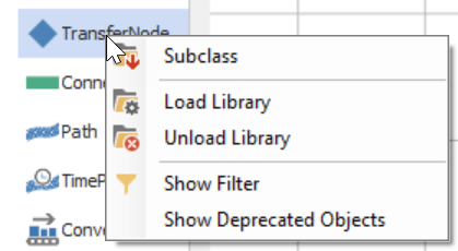
Figure 19.1: Sub-Classing the TransferNode
19.1.3 A "derived" version of the TransferNode class is placed in the [Navigation] panel as MyTransferNode. Right-click the new class and select the Model Properties option to display all of the properties.
- Change the Model Name property to DelayTransferNode.
- Change the Icon property to any appropriate icon (i.e., a PNG or bitmap file).276 The icon is the picture seen in the project window used to select the object. For example, the Delay.png file seen in Figure 19.2 will be used in the chapter.

Figure 19.2: Icon for the DelayTransferNode
- Under the "General" category, change the color of the new DelayTransferNode to something like maroon.277
- Select the new DelayTransferNode in the [Navigation] panel, and let's take a moment to look at the inherited processes and characteristics. Navigate to the "Processes" tab and see the processes (i.e., behaviors) in Table 19.1 that have been inherited from the parent TransferNode class.
| Process Event | Process Description |
|---|---|
| OnEntered | This process runs after the leading edge of an object (Entity, Transporter, or Agent) has entered the node. |
| OnEnteredFromAssociatedObject | This process runs after an Entity enters the node from another object (e.g., a Vehicle dropped it off). |
| OnEnteredParking | This process runs after the leading edge of an object (Entity, Transporter, or Agent) has entered the parking station. |
| OnEnteredToAssociatedObject | This process runs after an Entity enters the node and heads to an associated object. An object uses the node as its input node (e.g., entering the Server object.). |
| OnExited | This process runs after the trailing edge of an object has exited the node. |
| OnRunEnding | This process runs when the simulation ends. |
| OnRunInitialized | This process runs when the simulation starts initially. |
| OnEnteredParking | This process runs when the Entity or Transporter enters the parking station, ending the transfer. |
| RoutingOutLogic | A process used to handle the logic of routing objects out of the node (i.e., ride on a Transporter, by sequence, etc.) |
| TransferFailureLogic | If an object fails to transfer to an outbound link, it will destroy the object or park it if it fails (i.e., Transporters that cannot be destroyed). |
- Select the "Definitions" tab to access the characteristics of the node. Elements represent objects in a process that change state over time (i.e., statistics, timers, monitors, failures, etc.). There are two elements defined: a parking Station and a Routing Group.
- The ParkingStation station is used to house entities, operators, and transporters parked at the node. The station element will be discussed in more detail in the next chapter.
- The RoutingGroup element is used with a Route step to route an entity object to a destination selected from a list of candidate nodes. The TransferNode object uses a RoutingGroup element in its internal logic to determine where the entities will travel when they leave the node.
- The new sub-classed node inherits several properties and states and four events from the parent TransferNode, as described in Table 19.2.278
| Event | Event Description |
|---|---|
| CapacityChanged | The node’s capacity has changed. |
| Entered | An object’s leading edge has entered the node. |
| Exited | An object’s trailing edge has left the node. |
| RiderWaiting | An Entity is waiting for transport at this node. |
- Three string lists (i.e., EntityDestinationType, RideOnTransporterType, and ActionConditionType) have been defined and used in property dropdowns. The EntityDestinationType list is used to specify the property of how to route the entity to its next destination node (i.e., Continue, Specific, BySequence, SelectFromList, UseCustomRoutingGroup, and Destroy Entity). The RideOnTransporterType list allows the user to specify whether the entity must ride on a transporter to exit the transferNode. In contrast, the ActionConditionType is the condition type (NoCondition, IsEntity, IsTransporter, CustomCondition) used to compute Tally statistics at this node.
19.2 Modifying Processes and Adding Properties for the New Node
The new delay node sub-classed from the standard TransferNode will operate like the original node since nothing has been added or modified. The node needs to delay the objects that enter the node either individually or via a transporter.
19.2.1 Under the "Definitions" tab in the delay node, add an Expression property279 named DelayTime, which a user can use to specify the delay time for the entity. Specify the Default Value property to be zero while the Unit Type should be "Time" with Default Units of "minutes," as seen in Figure 19.3. Place the new property underneath the "Process Logic" category.
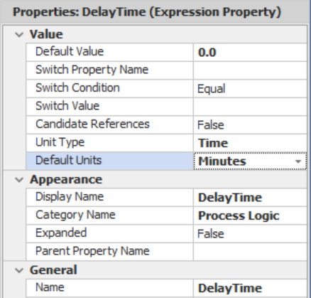
Figure 19.3: Inserting a Delay Expression Property
Every time an entity enters this transfer node either on its own or via an associated object, it should be delayed by the delay time expression property. Therefore, the OnEnteredFromAssociatedObject280 and the OnEntered processes will need to be modified to reflect this consideration. Currently, the processes are not editable, which can be seen by selecting the OnEntered process and noticing the steps and properties are grayed out. After selecting the process,281 click the Override button, allowing changes to be made as seen in . Once the process has been overridden, the Override symbol is placed under the process name to indicate it has been modified. Note: The Restore button can be used to return the process to its original state.
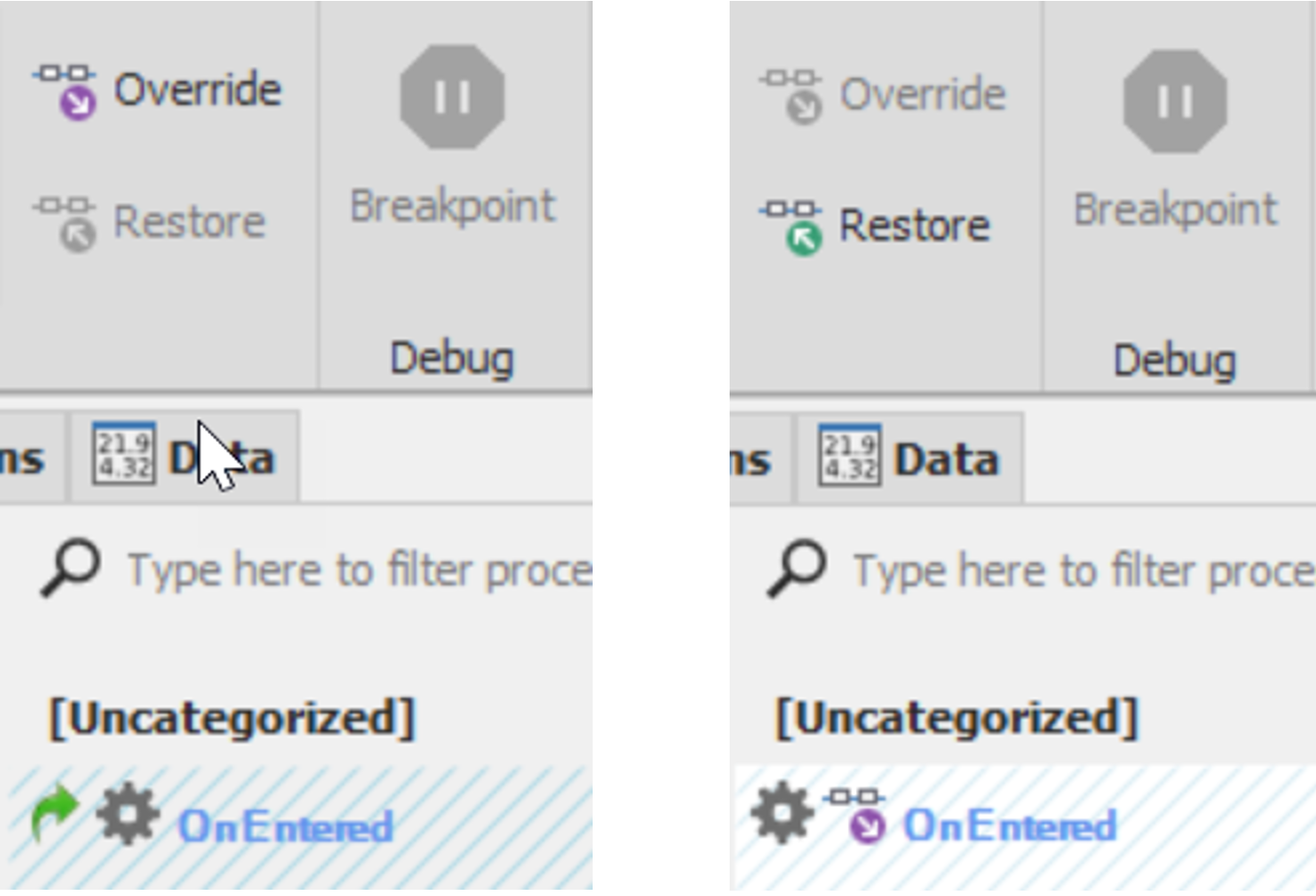
Figure 19.4: Overriding and Restoring Inherited Processes
The OnEntered process is relatively complex and has the following basic steps.
- On Entering State Assignments are performed.
- On Entering Tally statistics to be collected if specified.
- Fires the "Entered" Event.
- Then Execute the "EnteredAddOnProcess" that a user may have specified.
- Checks to see if a node is "Bound to an External Node" and, if so, transfers it to the specified parent external node.
- The Visit Node step is used to invoke the entity's OnVisitingNode process to indicate the entity has arrived at the destination node.
- If this entity is a transporter, transfer it to the outbound link since it does not go through the same logic, and if there is no outbound link, the transporter is sent to free space or processes a transfer error.
- If the entity is not a transporter, then it executes the RoutingOutLogic process to transfer the entity out of the node with the correct logic (i.e., uses the "Route" step in conjunction with the RoutingGroup element). If not riding on a transporter in routing out, then transfer to the outbound link occurs, and the prior logic applies.
19.2.2 Users may sometimes want to change the delay time based on some condition when they enter the node. Therefore, insert a Delaythe DelayTime reference set in the previous step, as seen in Figure 19.5.282 Under the "General" Section, the Name property can be specified as "DelayTime" for a better description.
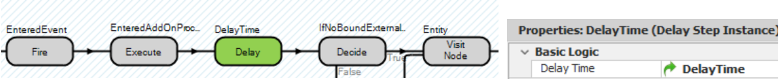
Figure 19.5: Modifying the OnEntered Process to Include the Delay
19.3 Creating a Model to Test the New DelayTransferNode
Now that the new delay transfer node has been created, it can be used in any model where the original TransferNode is used with the added benefit of delaying entities for some time as they enter the node. Figure 19.6 shows a network where we will test our new DelayTransferNode.

Figure 19.6: Building an Example to Test Our DelayTransferNode
19.3.1 Go back to the original Model by selecting it in the Navigation panel.
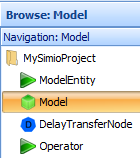
Figure 19.7: Navigating Back to the Original Fixed Model
As seen in Figure 19.8, the model will create an entity and then duplicate it, sending the original through a DelayTransferNode and the duplicate through a standard TransferNode. The time in the system will be used to illustrate the delaying behavior.
- Insert a new ModelEntity named EntParts.
- Insert a Source named SrcParts that creates EntParts.
- Add a Separator named SepCopy, which can be used to create copies of entities or to un-batch entities that have been combined/batched using a Combiner.
- Add a new DelayTransferNode named TDelay, which can be accessed via the [Project Library] panel.
- Add a normal TransferNode named TNormal
- Add a Sink named SnkExit.
- Connect the SrcParts to the Separator using a connector.
- Connect the parent output to your new TDelay and the member output to the TNormal node via TimePaths which takes five minutes for each.
- Connect both TNormal and TDelay to the Sink via ten-minute time paths.
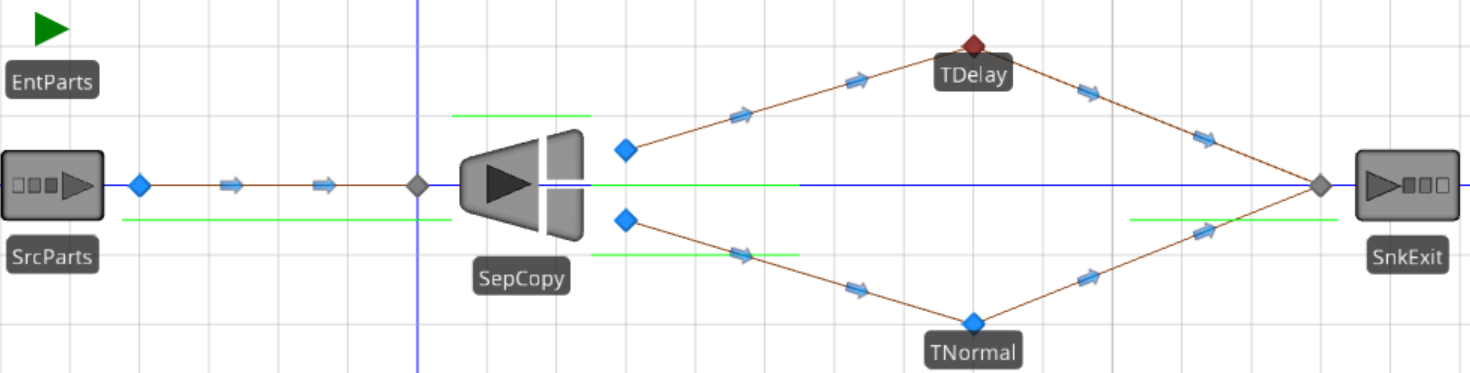
Figure 19.8: Model Used to Demonstrate the New DelayTransferNode
19.3.2 Configure all the fixed objects with the following parameters.
- Source: Parts should arrive at a constant interarrival time of five minutes.
- Separator: The Separation Mode property should be specified as "Make Copies," and the Copy Quantity property should be one, as seen in Figure 19.9. This will make one copy of the current entity. All properties of the entity will be copied. However, the entity's creation time is current and not necessarily the same time as the original entity. The original entity will flow out of the ParentOutput node, while the copy will flow out of the MemberOutput node.

Figure 19.9: Separator Properties
19.3.4 Let's add a status label to the Entity that displays its associated EStaTimeClock state variable. Select the EntParts object in your model and then choose the Status Label under the Attached Animation→Dynamic Text section.283 Draw a slender status label near the entity with the expression equal to String.Format(“{0:0.###}”,EStaTimeClock)284, as seen in Figure 19.10.

Figure 19.10: Creating a Status Label to Track the Part’s EStaTimeClock State
Figure 19.10: Creating a Status Label to Track the Part's EStaTimeClock State
19.3.5 Since the status label is attached to the ModelEntity, it will travel with it. Therefore, rotate (via Ctrl→Mouse), size, and move the label so it sits right on top of the entity, as seen in Figure 19.11 below.
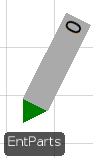
Figure 19.11: Attaching the Status Label to the Part Entity
19.3.6 Save and run the model to make sure it behaves as predicted.
19.3.7 The value of the EStaTimeClock state variable has not been updated at this point. Navigate to the "Processes" tab and create a new process named SetTimeClock. Insert an Assign step that sets the ModelEntity.EStaTimeClock to a new value of 60*Run.TimeNow285, which will set the variable to the current simulation time in minutes.
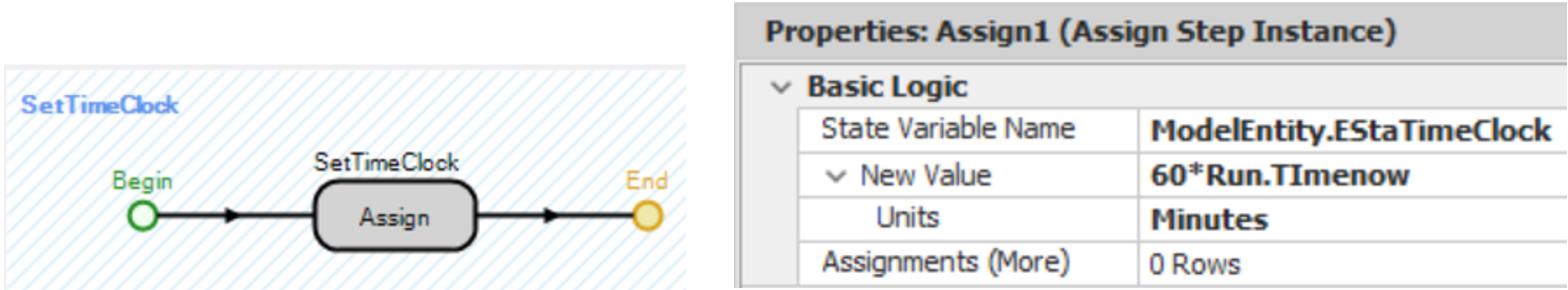
Figure 19.12: Creating a Generic Process to Set the Model Entity’s StaTimeClock
19.3.8 When the Parts exit the Separator through the Parent or Member output, the Parts EStaTimeClock variable needs to be set to the current time. Select the ParentOutput@SepCopy transfer node and specify the SetTimeClock process for the "Entered" add-on process trigger, which will assign the current simulation time to the EntPart's EStaTimeClock. Perform the same process for the MemberOutput@SepCopy "Entered" add-on process trigger.286
19.3.9 Repeat the process for the "Entered" and "Exited" add-on process triggers for both the TNormal and TDelay transfer nodes.
19.3.10 Save and run the model. Observe the time stamps as the entities leave the separator as well as the times to enter and exit the transfer nodes. You would think that the time stamps should be the same since the delay time is zero and whole numbers are used for the arrival and time paths. You may want to set a breakpoint on one of the nodes and then a single step until the entity leaves the transfer node.
19.3.10.1 Are the entering and exiting times different for the parts, and if so, why?
_______________________________________________
It seems there is a small amount of time being delayed in one of the transfer nodes compared to one other. They enter the nodes at the same time (i.e., at time ten on the left side of Figure 19.13) but appear to leave at slightly different times, as seen on the right side of Figure 19.13. However, transfer nodes take up zero space and should not have caused any delay (i.e., discrepancy). The time an entity enters the node should equal the time it leaves.
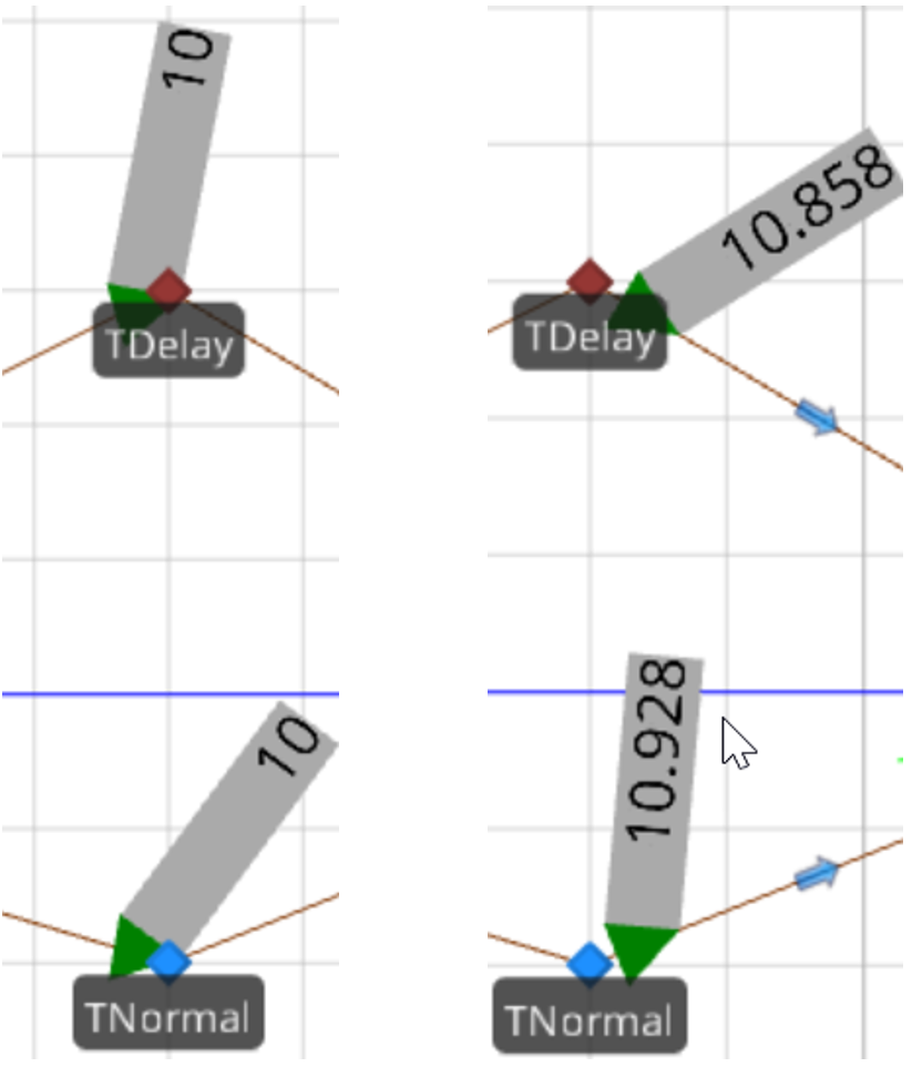
Figure 19.13: Showing Discrepancies Between Exited and Entered Times
The discrepancy deals with when the"Exited" process event is fired. This event will not fire until the trailing edge of the entity has left the node, which depends on the length of the entity and how fast the entity is transferred onto the link (i.e., a function of the entity's speed and the speed of the path its leaving and the one it is entering). The "Entered" process event is fired once the leading edge has entered the node. Therefore, when setting time stamps, the selected add-on process trigger should be based on the leading edge of an Entity. Figure 19.14 demonstrates that both entities enter the node at the same time. However, the smaller entity will exit the node first, as shown.
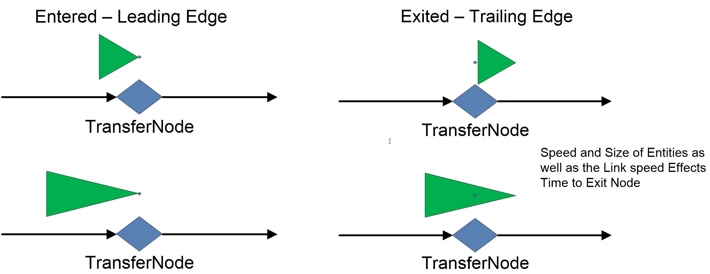
Figure 19.14: Demonstrating Entering and Exiting from Nodes
19.3.11 Reset (remove) the "Exited" add-on processes of both transfer nodes (i.e., TDelay and TNormal) and reset the "Entered" two outputs of the SepCopy to remove the add-on process trigger.287 Specify the SetTimeClock process for the "Entered" add-on process for each of the four-time paths leaving the two transfer nodes and the Separator.
You can also subclass any user created object as well.↩︎
Icons are typically 32 pixels wide by 32 pixels high. Many image editing software can create these icons (e.g., Photoshop, Paint or freeware GIMP program. (http://www.gimp.org)).↩︎
You cannot change the picture (i.e., diamond) because nodes are special objects that take up zero space in the actual system.↩︎
To access Inherited items, click on the
 to make the items visible.↩︎
The Expression Property allows the user to specify any mathematical expression similar to a Processing Time of the Server.↩︎
For example, the object is entering via transporter.↩︎
Select the Processes tab to access all the processes.↩︎
Right click on the property label to specify a referenced property.↩︎
We could put the expression in the Dynamic Label Text under the Animation section of the entity as well but this is more visible.↩︎
This will format the time clock to have three digits of precision.↩︎
Run.TimeNow is a function that returns the current time of the simulation in hours.↩︎
You can select them all and specify the “Entered” process at one-time.↩︎
Recall to reset a process trigger, right click the process and select the “Reset” item.↩︎