Simulation Modeling with Simio - 6th Edition
Chapter
17
Sub-Modeling: Cellular Manufacturing
Object-oriented simulation languages allow users to extend the base language by creating new objects through composition and extension/inheritance. Most object-oriented languages offer the ability to create new objects out of existing ones, referred to as composition. SIMIO provides the ability to create objects via composition and extension. This chapter will explore the easier object creation (i.e., the composition of facility models inside other models (sub-models).JJ
A manufacturing operation has ten multiple work cells, and each work cell consists of two machines connected by a short conveyor, as seen in Figure 17.1. A dedicated operator is needed to load parts into the machine for processing on the first machine and then to unload them from the second machine. The conveyor system will automatically transfer the parts from the first machine to the next machine. Some work centers (i.e., machines within the work cell) can handle multiple parts in parallel. Also, priority is given to unloading parts from the second machine to ensure parts are processed through the cell quickly. One way to do this would be to insert ten Machine A servers, ten Machine B servers, ten conveyors, and ten fixed resources that are seized and released. Since the work cells are the same, we can use composition to create a work cell object and then use it nine times to model the whole manufacturing system.
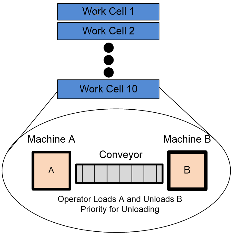
Figure 17.1: WorkCell Manufacturing Facility
17.1 Model of One Work Cell
Before building the larger model, working initially with a single work cell is better. Eventually, this model will become a building block (i.e., composition object) and is referred to as a “sub-model” (see Figure 17.2).
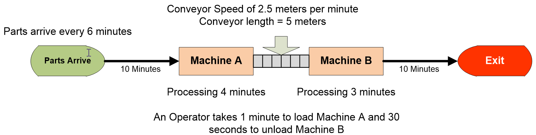
Figure 17.2: Individual Work Cell
17.1.1 Create a new project in SIMIO. Change the model name to WorkCell by changing the Model Name in the Model Properties.
17.1.2 Construct the model according to Figure 17.3.

Figure 17.3: Initial Two-Machine Model
- Add two servers named SrvMachineA and SrvMachineB. For now, the processing times should be four and three minutes.
- Connect these two machines with a five-meter conveyor with a speed of 2.5 meters per minute.
- Add a ModelEntity, Sink, and Source that generates arrivals every six minutes. Do not worry about naming since these are only temporary.
- Connect the Source to SrvMachineA’s input and the sink to SrvMachineB’s output node via ten-minute time paths.
17.1.4 The machines require an operator to load the part into the first machine, which generally takes one minute, and then to unload the part from the second machine, which takes approximately 30 seconds. Insert a new fixed Resource named ResOperator. Add an additional symbol to indicate working and color the iris green.
17.1.5 Add the “Before_Processing” add-on trigger for Machine A that will seize the”Specific” resource ResOperator, delay for a certain amount of time, and then release the specific resource. This process represents parts that enter processing at Machine A but need to be first loaded into the machine by the operator before being processed.
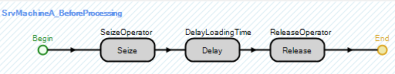
Figure 17.4: Process Logic to Seize and Release Operator to Load First Machine
17.1.6 The Delay Time property for the Delay step should be a referenced property. Right-click on the Delay Time and “Create a New Reference Property” named LoadDelayTime.
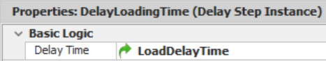
Figure 17.5: Specifying a Referenced Property as the Delay Time
17.1.7 Repeat the procedure for unloading parts out of the second server SrvMachineB. The only difference is that the name of the referenced property should be UnloadDelayTime, and the add-on trigger should be the “After Processing” trigger (i.e., SrvMachineB_AfterProcessing). Once the process has been created, copy and paste the process steps from the SrvMachineA_BeforeProcessing and create the new reference property for the Delay Time.
17.2 Creating the Sub-Model
The primary work cell model works correctly, but we must create the sub-facility model to turn it into an object we can use in other simulation models. To create the sub-model, an External view of the sub-model must be defined before you can use it as an object in other models similar to the Server, Source, etc.
17.2.1 Delete the Source, Sink, and ModelEntity from this facility model since they were only needed to test the logic of the two machines connected via a conveyor.
17.2.2 Since the WorkCell model will be used as a sub-model, none of the nodes in the model (i.e., Input@SrvMachineA or Output@SrvMachineB) are visible to the external model (i.e., models using the WorkCell object). Therefore, two external nodes need to be added to the external view of the object (i.e., Definitions→External section) to facilitate the flow of entities into and out of the sub-model.266
- Since entities entering the WorkCell object need to enter the input node of machine A (i.e., Input@SrvMachineA), right-click the BasicNode to bring up the sub menu seen in Figure 17.6 and select “Bind to New External Input Node” and then name the external node Input to be consistent.267
- Next, right-click the output node of SrvMachineB, but this time select “Bind to New External Output Node” and name it Output.
- By default, all objects (i.e., animated queues, objects, etc.) in the facility are visible to the external world as indicated by the “Externally Visible” button, which is toggled on, as seen in Figure 17.6. Toggle the externally visible button off for both the Input@SrvMachineA and Output@SrvMachineB nodes. This will make it easier to see our new Input and Output nodes.
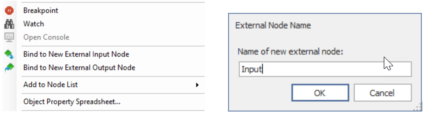
Figure 17.6: Automatically Adding External Nodes as Making Objects Visible to the External View
17.2.3 Navigate to the External panel underneath the Definitions tab and survey the external view, which includes the two external nodes named Input (a BasicNode) and Output (aTransferNode)268, as well as a symbol representing the model, as seen in Figure 17.7. Only the two nodes are accessible.
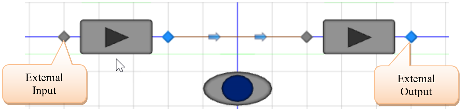
Figure 17.7: External View of the WorkCell Object
17.2.4 Select the Input node, which can be seen as an instance of the BasicNode Node Class. Generally, entities are transferred from this input node to a station. However, the sub-facility model does not expose a station. Therefore, these entities will be transferred to the input of the SrvMachineA. The Input Location Type property is set to “FacilityNode,” and the Node Name is the Input@SrvMachineA as in Figure 17.8. As entities flow into the Input of the WorkCell, they will be automatically routed to SrvMachineA.
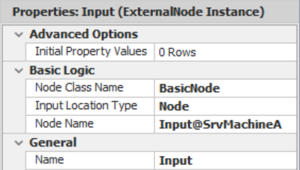
Figure 17.8: The Input Node
17.2.5 After selecting the Output node, you can see this is an instance of the TransferNode class to allow entities to be routed to their next destination once they leave the WorkCell (see Figure 17.9).

Figure 17.9: The Output Node
17.2.6 Entities that enter the external input node of the Workcell object will automatically be transferred to the input of the SrvMachineA via the Input node. When entities reach the output node of the SrvMachineB, they need to be transferred to the external output node (Output) defined in the external view. Switch back to the “Facility” tab and select the Output node of SrvMachineB (i.e., Output@SrvMachineB). Under the Advanced Options category, you can see that SIMIO automatically changed the Bound External Output property to specify the Output as the external node name property, as shown in Figure 17.10. Now, entities will automatically be transferred to the external Output when they reach the output of the SrvMachineB.
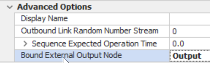
Figure 17.10: Connecting the External Node
17.3 Creating a Model using the WorkCell Sub-model
The WorkCell Sub-facility model has been built and can now be saved to a library and used as any other object that is part of SIMIO. We are going to develop our manufacturing systems using the WorkCell.
17.3.2 In the new model, insert a Source named SrcParts, a Sink named SnkExit, and a new work cell named Cell1, which is part of the Project Library panel. Connect the Source and the Sink to the WorkCell via ten-minute time paths, as seen in Figure 17.11.
17.3.3 Make the interarrival time of parts is Exponential with a mean of 5 minutes.

Figure 17.11: Simulation Model Using the New WorkCell Sub-Simulation Model
17.3.4 For Cell1, ensure the Load Delay Time property is one minute while the UnloadDelay time property is 0.5 minutes.
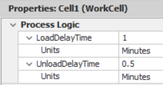
Figure 17.12: Setting the Properties of the WorkCell
17.3.5 Save and run the model for 24 hours, looking at the results. Notice that the statistics of all the pieces of the work cell are visible under the WorkCell object type.
17.3.6 Select the WorkCell Cell1 and choose a different symbol for animation purposes.269
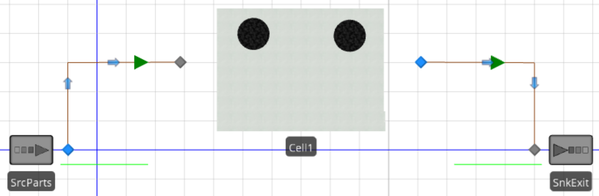
Figure 17.13: Changing the Symbol
17.4 Adding to the WorkCell Object
The internal view of the composition object (i.e., sub-model) is the object’s symbol, which removes the internal workings when replaced with a new symbol. In this simple example, showing the internal workings may make sense, but hiding the details of the sub-model in more complicated sub-models may be more beneficial (i.e., just having a plain symbol to represent the object). However, when using a different symbol, it would be helpful to see some indication of the locations of the entities (i.e., animated queues).
17.4.2 Go to the external view under the “Definitions→External” section; add four animation queues from the”Animation” tab on the ribbon for the new work cell object. One queue should animate the SrvMachineA.InputBuffer.Contents to represent entities waiting to be processed while both processing queues of each server (SrvMachineA.Processing.Contents and SrvMachineB.Processing. Contents) should be animated. Finally, the output buffer queue of the SrvMachineB is animated to animate entities waiting to leave the work cell (SrvMachineB.OutputBuffer.Contents).270

Figure 17.14: External View Showing the Four Animated Queues
17.4.4 Run the model by observing the animation of the WorkCell when a different symbol is used.
Currently, the entity will be hidden from the animation view when it is on the conveyor and waiting for processing at machine B or any other place with an animated queue associated with it. Since the animation of the internal submodel is not shown, we can reveal some of the behavior by placing labels that display the number of entities at the various locations. However, it would be helpful to have a representation of the number of parts currently being processed by the work cell either by machine A or B, as well as the number traveling on the conveyor and those waiting in the input buffer of machine B.
17.4.5 SIMIO has the ability to specify user-defined storages (queues). Select the WorkCell model in the [Navigation] panel and navigate to the Definitions tab. Under the Elements section, insert a new Storage element named StorageWorkCellInProcess. We will accept the default ranking rule of “FirstInFirstOut”.

Figure 17.15: Adding a Storage
17.4.6 Recall there are two process steps (i.e., Insert and Remove) that can be used to manipulate user-defined queues.271 Once the part enters processing at SrvMachineA, it should be inserted into the StorageWorkCellInProcess queue to indicate they have gone into processing. Add an Insert step after the operator is released in the processing with the Queue State Name property associated with the new user-defined queue WorkCellInprocess.Queue. The Object Type should remain the “AssociatedObject” because the token is associated with the part.272
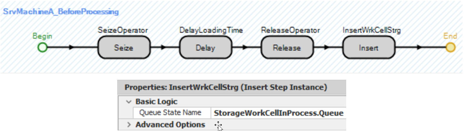
Figure 17.16: Using an Insert Step to Add Parts to a User-Defined Queue
17.4.7 Once the part has finished processing and removed from the machine, delete the part from the user-defined queue using a Remove step, as seen in Figure 17.17.
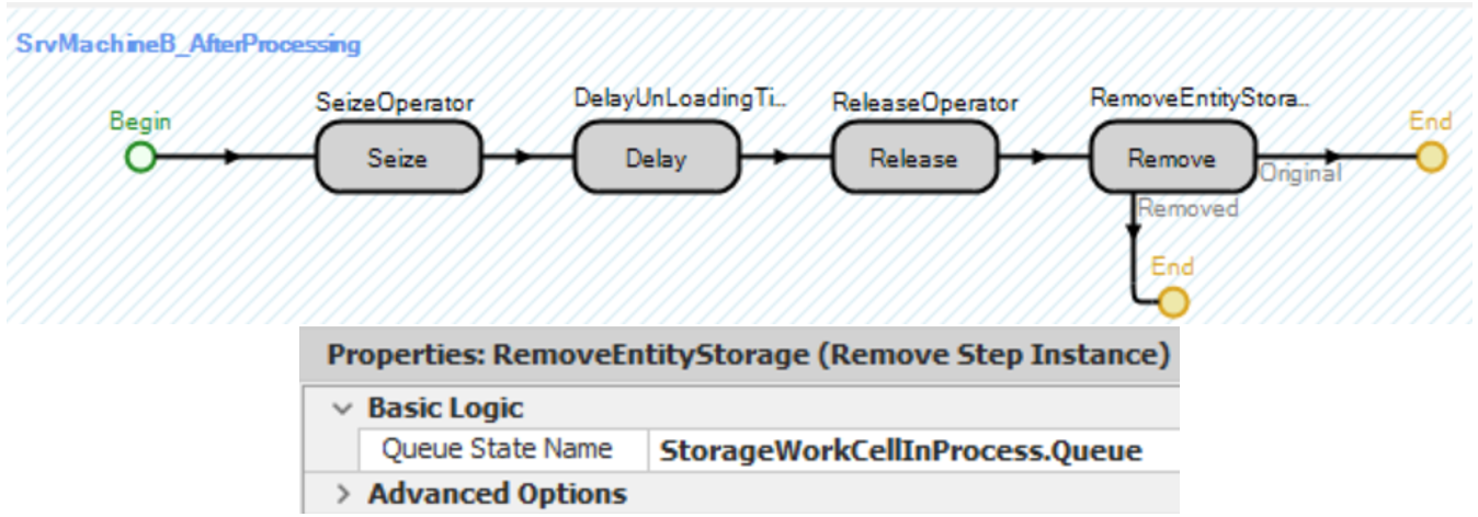
Figure 17.17: Using a Remove Step to Delete Parts from a User-Defined Queue
17.4.8 Go to the Definitions→External view section for the WorkCell Object and add an Animation Queue above the object that animates the StorageWorkCellInProcess.Queue and delete the Processing.Contents queues for machines A and B that were inserted earlier.
17.4.9 Return to the main model and manually insert an animated queue for Cell1, namely Cell1. StorageWorkCellInProcess.Queue. Recall none of the external view changes will appear for objects already inserted.
17.4.10 To see that the model is working correctly, insert five additional symbols for the Part’s coloring, each one with a different color. Set the Animation→Random Symbol property of the entParts to “True.” Change the mean interarrival time to be Exponential(2) minutes for the SrcParts.
17.5 Exposing Resource and Capacity Properties
Currently, the operator is hidden inside the Workcell sub-facility model and, thus, cannot respond to work schedules. Also, the capacity and processing times of the two machines are hidden from the user of the objects.
17.5.1 Return to the WorkCell model and select the Resource ResOperator. All fixed models have built-in properties of capacity type, capacity, ranking rule, and dynamic selection rules. Therefore, the ResOperator should be set equal to the WorkCell object’s properties. Select the ResOperator and specify all of the process logic properties to their associated WorkCell properties, as seen in Figure 17.18. When the user specifies these properties of the WorkCell, the ResOperator properties will be set to the same.
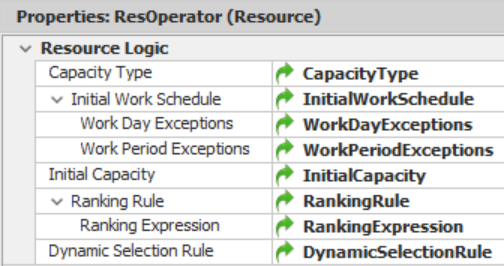
Figure 17.18: Exposing the Resource Capacity and Selection to the User
17.5.3 Create a new reference property for the Processing Time propertyfor each of the two servers named MachineAProcessingTime and MachineBProcessingTime, respectively, and the Initial Capacity property named MachineAInitialCapacity and MachineBInitialCapacity.
17.5.4 In the Definitions→Properties section, place all of these new properties into the “Process Logic” category and set the default units of the processing times to minutes.
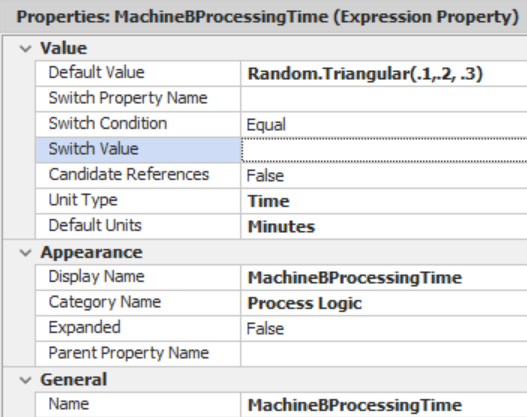
Figure 17.19: Machine B Processing Time Property Values
17.5.5 Return the main model, making sure to set the processing times of machines A and B to be equal to four and three minutes, respectively, if they are not already.
17.5.7 If you were only going to have one cell, then it does not make sense to take the time to create a sub-model object. However, the benefit of a sub-model object is that it can be reused repeatedly without repeating the same process logic and properties. Another advantage is if the logic changes or additional capabilities are needed, then changes need to be made in only one place.
17.5.8 Insert two new Workcell objects named Cell2 and Cell3 by copying the Cell1 object to include the same symbol with the same processing times of four and three minutes but make the capacities equal to two for the capacities for the two machines. Notice that the new animated queue has been automatically added.
17.5.9 Connect the Source and Sink via five-minute time paths to these new work cells and increase the arrival rate to two per minute.
17.5.10 Save and run the model, observing the results.

Figure 17.20: Demonstrating the Reuse of the WorkCell Object
17.5.11 Next, create a Data Schedule named SchedCell under the Workschedules view of the Data tab. Change the Standard Day such that there is a repeating schedule with three hours being “Off Shift” and three hours being “On Shift.” “On-shift” should have a capacity of “4” as seen in Figure 17.21.
17.5.12 Select all three work cells and specify the Capacity Type property to follow a WorkSchedule with the Work Schedule property the SchedCell as seen below.

Figure 17.21: Specifying the WorkCells follow a WorkSchedule
17.6 Passing Information between the Model and its Sub-Models
Sometimes, the sub-model must be constructed using information from the model before the model has been constructed. For example, suppose the WorkCell needs an operator for MachineA, but the main model supplies the operator and is unknown to the sub-model. The sub-model must be created knowing that an operator will be available, but it doesn’t know its exact specifications. Here, a property “reference” is useful for the sub-model, expecting the property instance to be supplied in the model.
17.6.2 Click on the SrvMachineA server and use the Secondary Resources section using the Resources for Processing specification to select a resource randomly from the ResourceList, as shown in Figure 17.22.

Figure 17.22: Specifying the Resource
17.6.3 Select the Model and add two resources named ResOperator1 and ResOperator2. Add a new list of objects within the Definitions tab and the Lists option. Call it GResourceList and have it contain the two operators.
17.6.4 Specify the GResourceList for the individual cell’s ResourceList property. Doing this will link the model list to each of the sub-model lists.
17.6.6 Currently, we do not know where the operators are working since they are working at the sub-model level. At the model level, add an Integer State Variable to the ModelEntity called EStaCellNumber, which will be used to identify the cell.
17.6.7 In the State Assignments section of the TimePaths between the SrcParts and the cells, use the Before Exiting specification to assign the cell number to the EStaCellNumber. Figure 17.23 shows the assignment on the path to Cell 3. Repeat for the other two cells.273
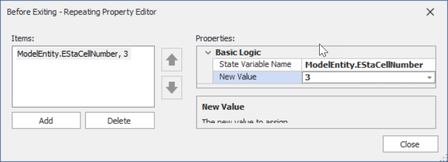
Figure 17.23: Assigning the Cell Number
17.6.8 Add Status Labels under each resource to display which cell the resource is working (refer to Figure 17.24). Show the status of each of the resources. The following expression is for ResOperator1, which first checks to make sure the Resource has been seized and, if it has, will display the entity’s cell number. Math.If(ResOperator1.ResourceOwners.NumberItems > 0, ResOperator1.ResourceOwners.FirstItem.ModelEntity.EStaCellNumber, 0)
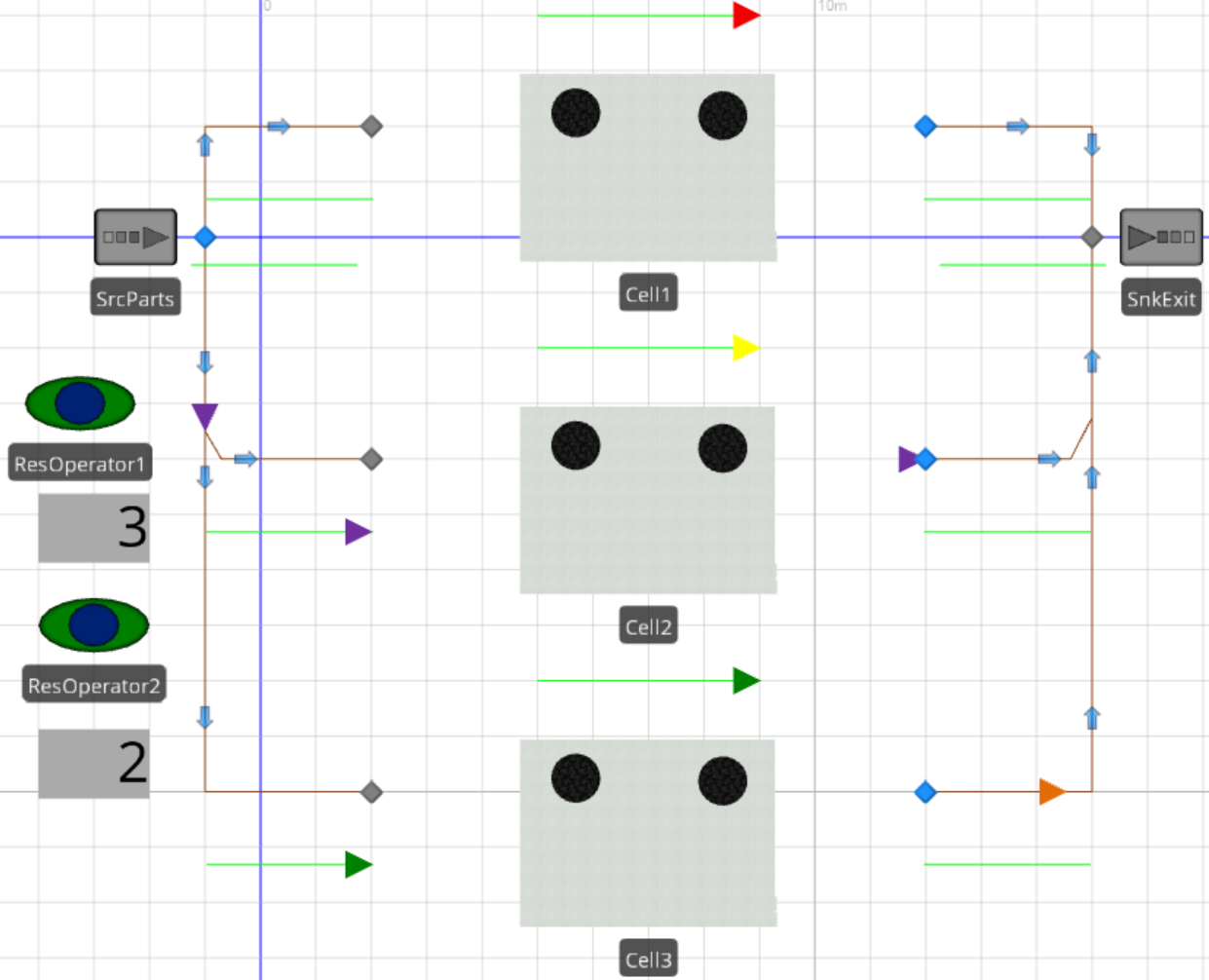
Figure 17.24: Communicating With the Sub-Model
All the basic objects (e.g., Source, Server, Workstation, etc.) have nodes in their external view that allow entities to flow into and/or out of the object.↩︎
These can be added manually from the External panel underneath the “Definitions” table however all of the property settings also have to be done manually.↩︎
The Input and Output nodes are on top of the picture of the nodes associated with the SrvMachineA and SrvMachineB. The model in the External view is only a picture of what the WorkCell will appear in other models.↩︎
In this example, a factory symbol was chosen and it was resized and rotated.↩︎
Draw the queues from right to left because the first point drawn will be the start/head of the queue.↩︎
These steps do not work on queues defined by SIMIO (which is quite a limitation).↩︎
The Rank Placement property can be used to specify the placement of the entity in the queue ignoring the overall ranking of the queue.↩︎
This is another great place to use a Tokenized process to set the cell number instead of using Before Exiting assignments especially if the number of work cells increased way beyond three.↩︎