Simulation Modeling with Simio - 6th Edition
Chapter
21
Continuous Variables, Reneging, Interrupt, Debugging: A Gas Station
Continuous variables are variables whose value can change continuously during the simulation (as opposed to discrete variables). Continuous variables in SIMIO can be “Level” or “Level with Acceleration” state variables – see “States” under the Definitions” tab in the “Continuous” section. When a Level state variable is created, you may also specify the rate of change, called the Initial Rate Value property, and its initial state, which is called the Initial State Value property. Level with Acceleration variables in addition to specifying the rate of change and the initial state, you may also specify the acceleration rate, called the Initial Acceleration Value property, as well as the length of the acceleration via the Initial Acceleration Duration Value. Unlike discrete state variables, continuous state variables can change continuously based on the rate and acceleration.
21.1 Simple Tank295 Manual Process
21.1.1 Create a new model. We are going to manage a simple gasoline tank by changing its rate value. We will assume the tank volume is between 0 and 100 gallons.
21.1.3 Create a new symbol named TankSymbol to associate with the tank (from the Project Home→New Symbol→Create Symbol), such as the one in Figure 21.1. The symbol that represents the interior is a square with a height of ten meters (whose height determines the content/level of the tank). Add a Gold Comb texture to give it the appearance of gasoline for both the top and the sides.
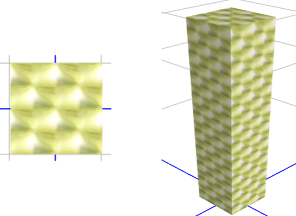
Figure 21.1: 2D and 3D Representation of the Tank Symbol
21.1.4 Next, use the TankSymbol as the symbol for the ResTank Resource.296 Once this is done, draw a static “case” around it so you can see the level of the tank in 3D, as shown in Figure 21.2. The case is made from a thick “Polyline,” leaving a small opening in the front to see the tank's level. The polyline also needs a height of ten meters.
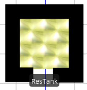
Figure 21.2: Tank Symbol
21.1.5 Now add a Level continuous state variable named GStaLevelConTank from the Definitions→States section. Let’s set the Initial State Value to 0 and the Initial Rate Value to 0. A negative rate value means the tank is being drained, while a positive value means it is being filled.
21.1.6 When we need to modify a parameter for a model, it is convenient to specify a model property rather than specifying a constant. Doing so also helps in eliminating mistakes by using the same symbolic name for a particular value. Therefore, a minimum and maximum level for the tank should be defined as a standard real property named TankMin and TankMax.297 For these two properties, the Unit Type should be “Volume” and Default Units equal to “Gallons.” Add two “Expression” standard properties named RatePositive and RateNegative to represent the rate at which the tank will fill up and the rate at which the rate will be emptied. For these two properties, the Unit Type should be “VolumeFlowRate” and Default Units equal to “Gallons per Hour.” Place each property into a new Tank Category.
21.1.8 Now add two Monitor Elements named MonTankEmpty and MonTankFull. These Monitors will detect the crossing of the GStaLevelConTank at the TankMin and TankMax levels, respectively.
21.1.9 For the MonTankEmpty Monitor, set the properties as shown in Figure 21.3.
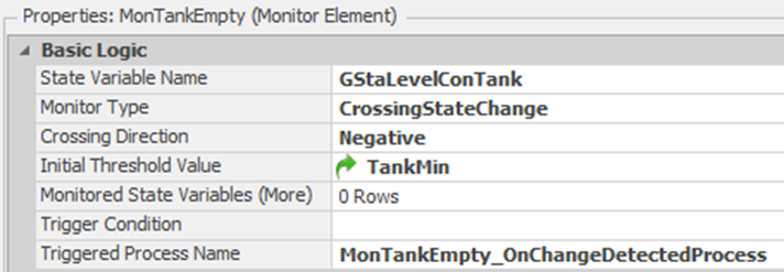
Figure 21.3: TankEmpty Monitor Specification
21.1.10 And for the MonTankFull Monitor, see Figure 21.4 for the property settings.
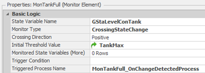
Figure 21.4: *MonTankFull Monitor Specification
21.1.11 Create new processes for the two On Change Detected Process add-on process triggers, which are defined in Figure 21.5 and Figure 21.6.298
21.1.12 The MonTankEmpty_OnChangeDetectedProcess process is called when the tank empties (i.e., the GStaLevelConTank reaches zero). We will need to stop emptying the tank, have a small delay before beginning to fill, and then start filling, as seen in Figure 21.5.
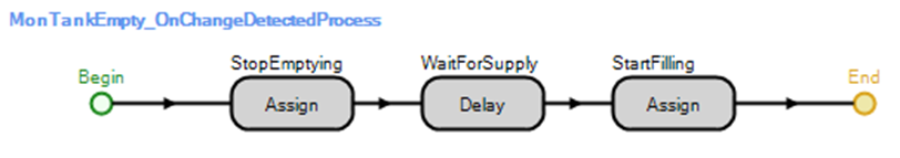
Figure 21.5: Process Called When Tank Empties
- The first Assign step sets both the GStaLevelConTank.Rate to “0,” which stops the Level state variable from changing and sets the ResTank.Size.Height to “0”.
- Use the Delay step to force a 0.2 hour delay before the tank begins to fill again.
- The final Assign step sets the GStaLevelConTank.Rate to its maximum value of RatePositive which will allow the tank to start to fill since it is a positive value.
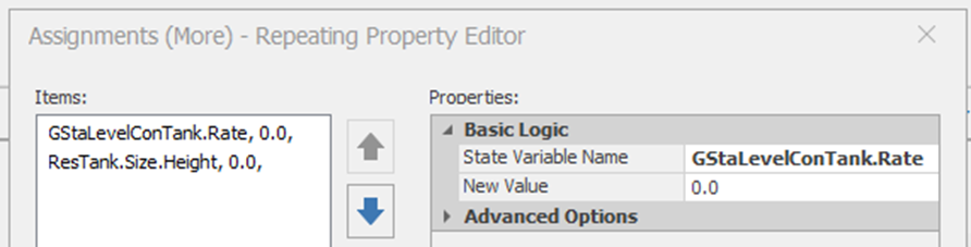
Figure 21.6: Assigning the Rate and the Height
21.1.13 The MonTankFull_OnEventProcess is called when the tank fills to the maximum level. Once it reaches this level, stop filling, force a small delay before allowing it to empty, and then allow the emptying to start, as seen in Figure 21.7.
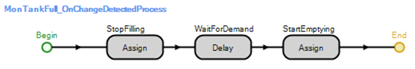
Figure 21.7: Process Called When Tank Fills
- The Assign step sets the GStaLevelConTank.Rate to 0. A 0.1 hour delay is assumed before the tank can start emptying, and then the last Assign step will set the rate to a negative value to allow emptying (i.e., set the GStaLevelConTank.Rate to the RateNegative).
21.1.14 Finally, we need to take care of the “height” of the tank animation. We will do that in the OnRunInitialized process for the model, which will run when the simulation starts. From the “Processes” tab, select the OnRunInitialized process from the “Select Process” drop-down.
- This process should Execute299 the MonTankEmpty_OnEventProcess once to initialize the tank for filling. Then, it will Delay for one minute and then Assign the ResTank.Size.Height to GStaLevelConTank /(TankMax/10) as in Figure 21.8.
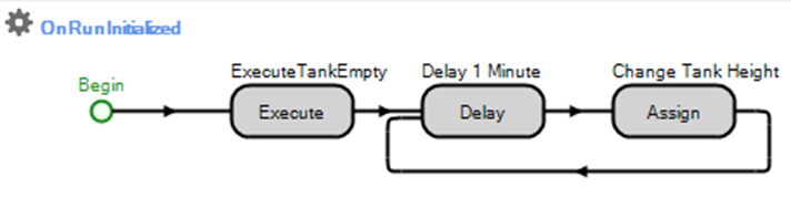
Figure 21.8: Changing the Height of the Tank
- Notice that the system loops continuously every minute, updating the tank height for animation purposes. Do this by grabbing the “End” point and dropping it on top of the Delay step. Therefore, the token will continually loop through these steps until the simulation stops.
21.1.15 For the tank level to show in the animation, the Current Symbol Index in the “Animation” section of the ResTank resource must be set to zero, so the OnRunInitialized process is the only specification to change the height. Select the ResTank Resource, add an additional symbol, and then set the Current Symbol Index property to zero.
21.1.16 To complete our animation, add six Status Labels from the Animation tab, as seen in Figure 21.9, where the expressions are GStaLevelConTank.Rate *264.1720524, GStaLevelConTank * 264.1720524, and ResTank.Size.Height, respectively300. Also, for the word Status labels, change the background to white.
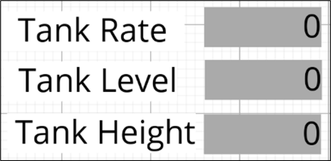
Figure 21.9: Adding Status Labels
21.1.17 Next, add a Status Plot of GStaLevelConTank vs. Time (hours) – see Figure 21.10. Change the Title, x-axis label, y-axis label, text scale, and the time range to plot (i.e., 2 hours) from the Appearance tab.
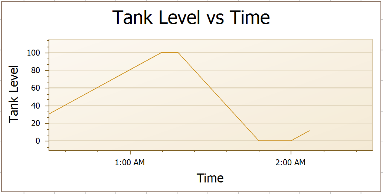
Figure 21.10: Status Plot
21.1.18 Also, a Circular Gauge (from the “Animation” panel) may be placed on top of the tank, as seen in Figure 21.11.301 It is a way to visualize the tank level in 2D. After adding the circular gauge with the correct style, under the Scale section’ set the Minimum property to zero, the Maximum property to 100, and the Ticks to 11. The Expression should be the level state of the GStaLevelConTank.
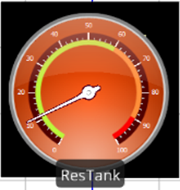
Figure 21.11: Adding a Circular Gauge the Current Tank Level
21.2 Simple Tank Revisited using the Flow Library
SIMIO provides a [Flow Library] to assist in handling pipes (i.e., flows) and tanks. The library provides a Flow Source for creating flow entities, Flow Sink, Tank, FlowNode (i.e., regulator), and Flow Connector used to connect FlowNodes. We will model the simple tank again using the [Flow Library], as seen in Figure 21.12
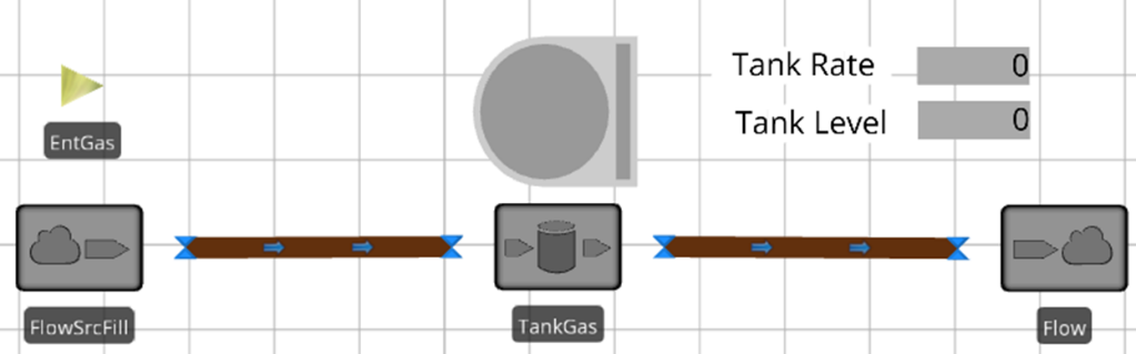
Figure 21.12: Simple Tank using the SIMIO Flow Library
21.2.1 Insert a new fixed model named TankFlow.302 Copy the four properties (i.e., TankMax, TankMin, PositiveRate, and NegativeRate) from the previous model and set their values as seen in Figure 21.13.303
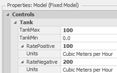
Figure 21.13: Setting up the Properties
21.2.2 Insert a new FlowSource named FlowSrcFill, which will be used to fill the tank.304 Select the output FlowNode Output@FlowSrcFill and change the Initial Maximum Flow to RatePositive (see Figure 21.14).
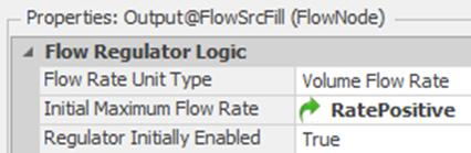
Figure 21.14: Setting the Correct Unit of the Output Flow
21.2.3 Insert a new ModelEntity named EntGas. Change the texture of the entity to the Gold Comb texture as before to cause the tank to fill up with gas.
21.2.4 Next, add a Tank named TankGas, which will hold the gasoline flowing from the FlowSource. Set the Initial Volume Capacity and High Mark to TankMax as well as the Low Mark to TankMin, as shown in Figure 21.15. Tanks have the ability to specify the capacity as well as have five different level marks (i.e., low-low, low, middle, high, and high-high marks) which will trigger processes when the tank reaches these levels. You should shrink the size of the tank animation to be smaller so you can see the tank filling and emptying easier.
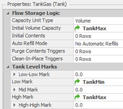
Figure 21.15: Setting up the 100 Gallon Tank
21.2.5 Select the Output@TankGas FlowNode and set the Initial Maximum Flow Rate to 200 gallons per hour, which represents the emptying rate.305 Also, set the Regulator Initially Enabled to “False” to indicate the regulator is closed and, therefore, not flowing (i.e., emptying), as seen in Figure 21.16.
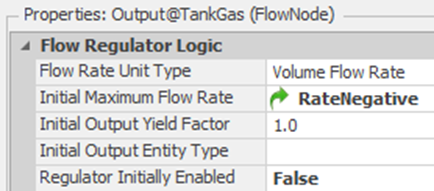
Figure 21.16: Specifying the Tank Emptying Rate
21.2.8 Copy the Tank Rate and Tank Level status labels as well as the status plot from the previous model. Change the expressions to TankGas.FlowContainer.Contents.Volume.Rate * 264.1720524 and TankGas.FlowContainer.Contents.Volume * 264.1720524 for the rate and tank level, respectively. Let the plot expression be the same as the tank-level expression.
21.2.9 Save and run the model. You may need to modify the speed factor to 100 to see the tank level rising.
21.2.9.1 What happens when the simulation runs with regard to the tank and the two FlowConnectors?
_______________________________________________
21.2.10 Once the tank fills up, the flow from the FlowSrcFill stops flowing, but the tank does not empty as the Output@TankGas regulator is not enabled. When the tank fills up, we need to delay for 0.1 hours and then open up this regulator while shutting down the regulator at Output@FlowSrcFill. Under the Tank Level Rising category, insert the Tank Full Add-on Process Trigger, as seen in Figure 21.17.306 The FlowNodes contain a Regulator element, which can be opened and closed to control the flow.

Figure 21.17: Shutdown the Flow Source and then Open up the Tank Output
21.2.11 Once the tank empties, we need to shut down the outflow regulator of the tank, delay for 0.2 hours, and then open up the regulator at Output@FlowSrcFill to start filling. Under the Tank Level Falling category, insert the Tank Empty Add-on Process Trigger, as seen in Figure 21.18
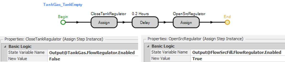
Figure 21.18: Shutdown the Outflow from the Tank and Start the Source Flow
21.3 The Gas Station
A gas station has four gas pumps, which dispense the same grade of gas. All the gas pumps pump their gas from a single tank in the ground. Cars arrive and obtain gas from any of the four pumps. If the ground tank is depleted to 100 gallons, the pumps are closed, although any car currently being filled finishes. Any cars in line will stay in line, but newly arriving cars will balk (i.e., leave). A tanker truck comes by periodically to refill the ground tank. As soon as the ground tank is full (i.e., 10,000 gallons), the pumps are open again to deliver gas.
This problem can be approached in several ways. Again, a continuous variable (i.e., tank) will be used to model the ground tank, and we will let the cars and the tanker truck change the inflow and outflow rates to the tank. The cars and the tanker truck will be our active entities. The amount of gas any car needs is assumed to be Triangular(4, 9.5, 25) gallons. The rate that any car can pump gas is Triangular(125, 150, 200) gallons per hour. The tanker will fill the tank at 20,000 gallons per hour.
21.3.1 We will modify the model of the simple tank from the previous section. Add two Sources, one Server, three Sinks, and two ModelEntities named EntCars and EntRefillTrucks, as illustrated in Figure 21.19.
- EntCars arrive Exponentially every 1.5 minutes beginning at time 0.1, while the EntRefillTrucks arrive Uniformly between 6.75 and 8.25 hours apart.
- Use Connectors to link all of the objects associated with the cars together. Make the link between SrcTanker and SnkTankerLeaves a Path.307
- Make sure each of the sources creates the correct entity type. Also, change the picture of the EntRefilTrucks to be a tanker308 and the EntCars to have four and six different car pictures randomly chosen (i.e., set the Random Symbol property to “True” under the Animation section).
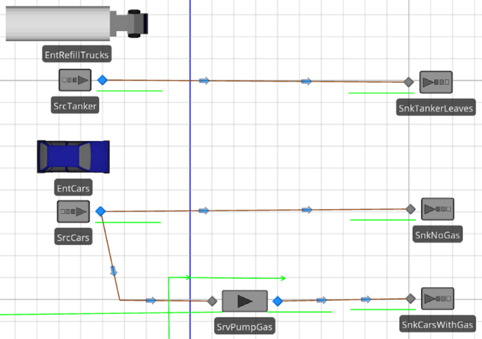
Figure 21.19: Model Structure
21.3.2 Define a new Discrete Integer state variable for the main Model named GstaPumpOn to model whether the pumps are on or off. A value of one means “on,” and zero means “off.” Set the Initial State Value property to zero.
21.3.3 Set the Initial Contents property of the TankGas to be TankMin, as shown in Figure 21.20.
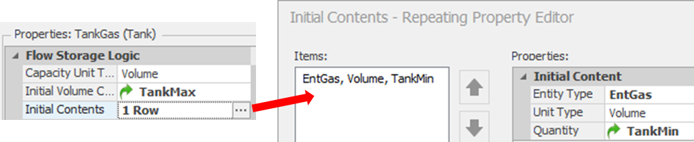
Figure 21.20: Setting the Initial Amount of Gas in the Tank
21.3.4 For the Model, change the TankMax and TankMin properties to 10,000 gallons and 100 gallons, respectively (see Figure 21.21). By setting the low mark value to 100, we will not allow our tank to empty completely since cars may still be getting gas when the tanker arrives. Change the PostiveRate and the RateNegative model properties to 20,000 and Random.Triangular(100,125,175) gallons per hour to represent the rate a car will empty the tank.
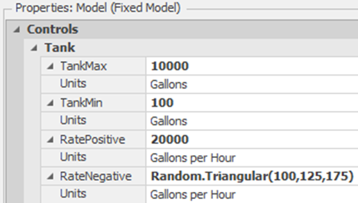
Figure 21.21: Setting the Rates and Initial Values of the Tank
21.3.6 Since the cars arriving will set the outflow rate, we need to set the Initial Maximum Flow Rate of the Output@TankGas to “0” Gallons per hour.
21.3.7 When cars are created by the source, define a process in the Created Entity add-on process trigger as in Figure 21.22, which assigns the car characteristics.309
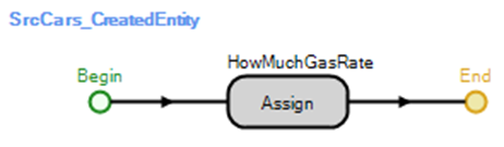
Figure 21.22: Cars Leaving the Source
The Assign step should set the following two state variables making sure the rate is negative, as seen in Figure 21.23.
ModelEntity.EStaGasNeeded = Random.Triangular(4,9.5,25) ModelEntity.EStaCarPumpingRate = RateNegative
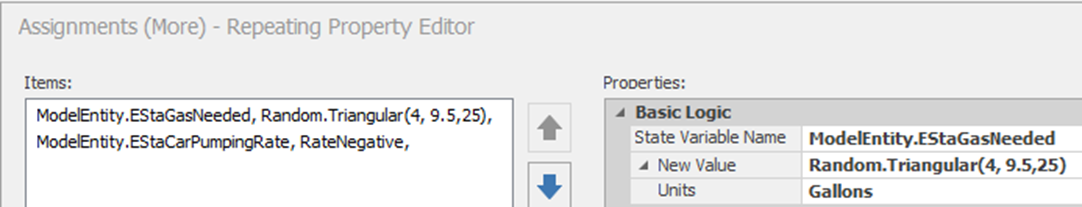
Figure 21.23: Specifying Gas Needed and the Pumping Rate of Each Car
21.3.8 Set the Processing Time property (in Hours) in the SrvPumpGas server to be the following.
ModelEntity.EStaGasNeeded/ModelEntity.EStaCarPumpingRate
This expression takes into account the amount of gas needed divided by the rate at which the customer can pump it. Make sure to change the Units to “Hours” and do not use the default of “Minutes.” Be sure that the Initial Capacity property of the SrvPumpGas server is set to “4” to indicate room for four cars.310
21.3.9 If the pumps are on, cars will be routed to the pumps and if they are off, they will be sent directly to the SnkCarsNoGas. The selection link weights on the paths leaving the source are defined as follows to ensure that one path will have a weight of one and the other one a zero.
- For the connection to SnkCarsNoGas, set the Selection Weight property to 1 - GStaPumpOn.
- For the connection to SrvPumpGas, the Selection Weight should be GStaPumpOn.
21.3.10 All discrete event simulation languages use events, and the user can define their own events in SIMIO. Under the “Definitions” tab, add a new Event named EvntStartPumps, which will allow entities to wait until the pumps are started up after they have been turned off to start pumping again.
21.3.11 Consider what happens when the tanker truck arrives, as shown in Figure 21.24. The tanker truck will turn off the pumps and start filling the tank at 20,000 gallons per hour. The tanker truck will continue to fill until the tank is full (i.e., the monitored MonTankFull reaches its threshold). Use the Entered add-on process trigger for the input node of the SnkTankLeaves (i.e., when the truck entity enters the sink).311
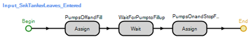
Figure 21.24: Tanker Truck Leaves
- In the Assign step, set the GStaPumpOn state variable to zero, turn off the flow Regulator of the Tank, and turn on the Regulator associated with the FlowSource, as seen in Figure 21.25.
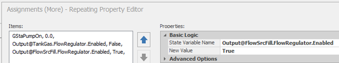
Figure 21.25: Setting the Pump to Off and Filling the Tank
- The Wait step delays the truck until the tank is filled. The full tank will be signaled by an event called EvntStartPumps (see Figure 21.26).
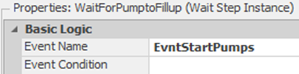
Figure 21.26: Waiting for EvntStartPumps to Continue
- Once the tank has filled up, we need to turn the pumps on, shut down the FlowSource Regulator, and enable the tank regulator to start again (see Figure 21.27).
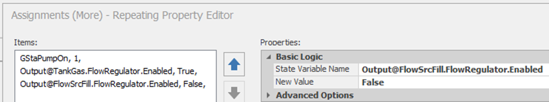
Figure 21.27: Turning On Pumps and Shutdown Filling the Tanks
21.3.12 When the pumps are off, new cars that arrive will leave the system. However, cars that are currently in line and/or filling up will remain. Those that are currently filling up will finish, but no other car should be allowed to start filling. Therefore, within the SrvPumpGas server, consider first when the processing of a car filling its individual tank begins (see Figure 21.28). Insert the Before_Processing Add-On Process Trigger with the following logic.
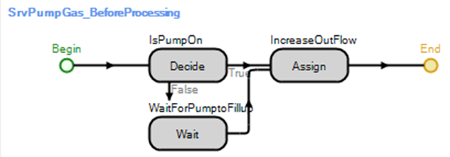
Figure 21.28: Processing Begins at the Pump
When the Before_Processing add-on process trigger starts: Decide if GStaPumpOn == 1
If the pumps are off (i.e., “False” branch), then “Wait” for the event EvntStartPumps.
Otherwise, if the pumps are on, enable the TankGas FlowRegulator (i.e., Output@TankGas.FlowRegulator.Enabled = True and change the tank emptying rate via an Assign step by adding the outflow due to the car being filled to the current rate: Output@TankGas.FlowRegulator.CurrentMaximumFlowRate = Output@TankGas.FlowRegulator.CurrentMaximumFlowRate + ModelEntity.EStaCarPumpingRate.
21.3.13 When the car finishes (i.e., processing) at the pump (i.e., After_Processing add-on process trigger for the SrvPumpGas), refer to Figure 21.29, we need to remove the outflow due to the car being filled (i.e., reduce rate). Use the Math.Max to ensure that you never go below zero.
Output@TankGas.FlowRegulator.CurrentMaximumFlowRate = Math.Max(0, Output@TankGas.FlowRegulator.CurrentMaximumFlowRate - ModelEntity.EStaCarPumpingRate)
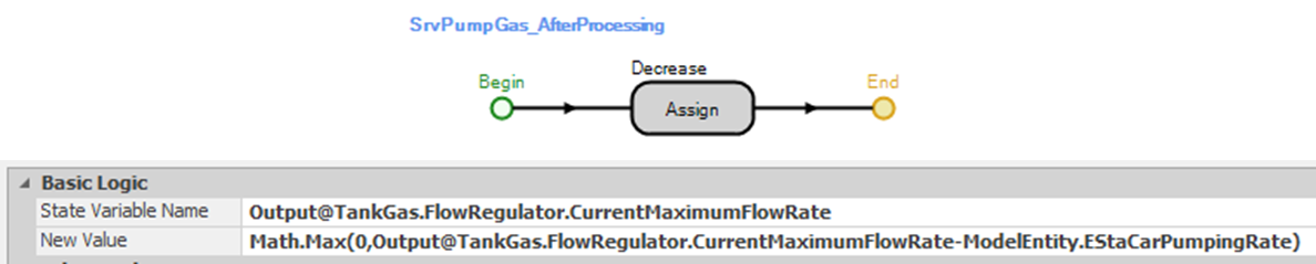
Figure 21.29: Car Finishes at Pump Decrease Rate
21.3.14 Next, take care of the process when the Tank reaches the low mark of 100 gallons. For the TankGas, insert the TankGas_TankLevelFallingBelowLowMark add-on process trigger and an Assign step that will set the GStaPumpOn to “0”, as shown in Figure 21.30.

Figure 21.30: Turn off the Pumps so Cars will Balk
21.3.15 For the TankGas_TankEmpty (see Figure 21.31), we need to disable the tank’s outflow (i.e., set Output@TankGas.FlowRegulator.Enabled to “False” and then set the rate to zero (i.e., Output@TankGas.FlowRegulator.CurrentMaximumFlowRate=0.0).
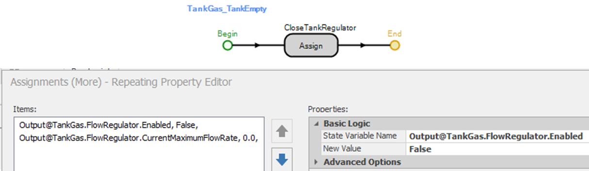
Figure 21.31: Tank is Empty
21.3.16 For the TankGas_TankFull event (see Figure 21.32), it should turn the pump on and let any cars waiting as well as the refill truck, know that the filling process has been completed. Use an Assign step to set the GStaPumpOn to “1” and then use the Fire step to “Fire” the EvntStartPumps event.

Figure 21.32: Tank is Full
21.3.17 When the event EvntStartPumps is fired, the truck waiting for the tank to fill is activated, and the cars waiting at the pumps will be activated. If these should be activated differently, then the process needs to be modified.
21.3.18 Save and run the current model for 48 hours.
21.3.18.1 Does this system seem to work (i.e., how many cars get no gas versus those that do)?
_______________________________________________
21.4 Reneging the Cars When the Pump Goes Off
The previous model assumed that when the tanker arrived and shut the pumps off, the cars at the pumps would continue to wait until the pumps were turned back on. Let’s modify the model so that all cars waiting at the pumps would renege (that is, leave).
21.4.1 Add a Sink to your model named SnkCarsRenege, which will automatically generate statistics for the reneging cars but does not need to be connected (see Figure 21.33).
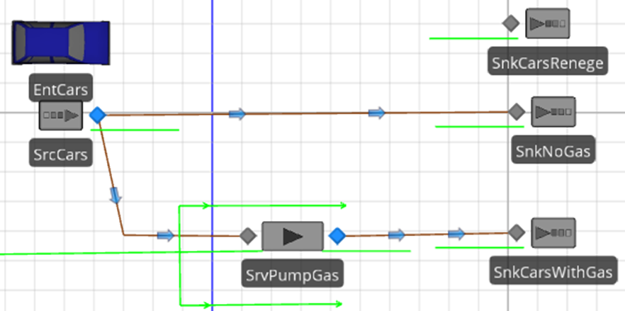
Figure 21.33: Adding a new Sink that is not Connected via a Path
When the tanker arrives, the cars waiting for a pump should be removed from the input queue of the SrvPumpGas. After the pump is turned off, insert a Search step that can search a collection of objects in a Table, a List, an instance of an object, a queue, and objects seized by the parent or associated object. In this case, set the Collection Type to “QueueState” and the Queue State Name to SrvPumpGas.AllocationQueue, which will search the cars waiting in the input buffer to be processed at the pump. See Figure 21.34.
- The search needs to return all the cars waiting; therefore, set the Limit property to “Infinity”. The Match Condition will allow searching for certain objects that have to be true for the item to be selected. In this case, we could have been left blank to return all entities in the queue. However, if you chose paths to link the objects and a car was on the link and arrived at the same time the tanker arrived, then there could be a car that has seized the pump but is waiting in the “Wait” state for the pump to come on and therefore we don’t want to remove any cars that have already seized a pump. For each car (i.e., EntCars) found, a new Token associated with the found car is sent down the “Found” path, while the original Token will eventually continue the “Original” path once all items have been found312.

Figure 21.34: Reneging all Cars Waiting for Gas when the Pump goes Off
21.4.2 Insert a Remove step to remove the current car associated with the “Found” Token from the SrvPumpGas.AllocationQueue. A Token associated with the removed item will exit out the “Removed” path.
21.4.3 Now insert a Transfer step that will move the car (i.e., ModelEntity) to the SnkCarsRenege by specifying the Node Name as Input@SnkCarsRenege as the node to send these cars. The car is currently in the InputBuffer Station, so this step needs to transfer the entity from the current station to the node specified, as seen in Figure 21.35.

Figure 21.35: Transferring the Cars to the Renege Sink for Statistic Collection
21.5 Interrupting the Cars When the Pump Goes Off
In the previous model, the cars waiting at the pump reneged when the pump was turned off, and we had already not allowed other cars to arrive at the gas pumps while the pumps were off. The cars already in service getting gas when the pumps go off were allowed to continue to fill up their car and then leave. Suppose now we want the model to interrupt the cars in service and deny them further use of the pump when the tanker arrives. These interrupted cars will leave through the SnkCarsRenege Exit as well.
21.5.1 To interrupt a process that is currently being delayed, insert an Interrupt step before the Search step, as seen in Figure 21.36 with specifications in Figure 21.37.
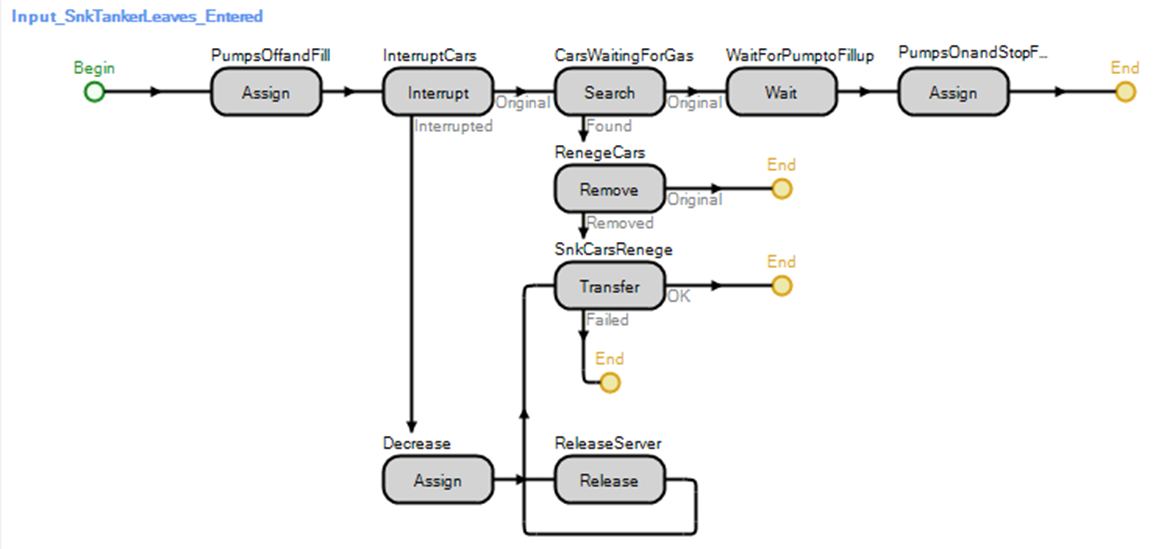
Figure 21.36: Adding the Interrupt to Force Cars Currently Processing to Renege
- Use the Process Name SvrPumpGas.OnEnteredProcessing which is the process that runs the Delay step (i.e., processing of the cars). Notice that we “EndProcess” for the interrupted processes and we establish a Limit of “4” since there are four pumps potentially in operation.
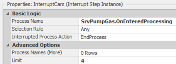
Figure 21.37: Interrupting the Cars Getting Gas
- Copy the Assign step from the step SrvPumpGas _AfterProcessing to the “Interrupted” branch, which will decrease the flow rate of each car. Then, connect the Assign step to the Transfer step that was used previously to force the cars to exit the reneging sink (i.e., SnkCarsRenege).
- Insert a Release step that will release a Specific resource (i.e., SrvPumpGas), as shown in Figure 21.38.
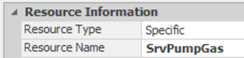
Figure 21.38: Releasing the Server SrvPumpGas after Interruption
21.6 Using Entities that Carry a Tank
In our gas scenario, there are really three distinct systems (i.e., the cars and the pump, the refill tanker, and finally, the continuous gas tank system). The first two systems are discrete systems that interact with the continuous system by turning on and off the regulators as well as changing the flow rate. The [Flow Library] provides several other flow objects that combine discrete and continuous together, as seen in Table 21.1. Currently, the tanker truck arrives and causes the FlowSource to fill up the tank at a certain rate till it is full. We assume the tanker has enough gas to fill the tank till it is full. However, the tanker truck can only carry about 4500 gallons of gas. Now, we will assume that we own one tanker that has a volume capacity (i.e., actually caries the gas) that will travel between the refill station and the gas station, filling the tank with its capacity. The tanker can move faster when it is empty on the return trip back to the refill station.
| Flow Object | Description |
|---|---|
| ContainerEntity | A ModelEntity that contains a Tank which is transported with the entity. |
| Filler | This object behaves in a similar fashion as the Combiner. Instead of combining a parent and member entity together, the object combines (i.e., fills up the tank) a discrete container entity with a flow. |
| Emptier | This object behaves in a similar fashion as the Separator does for entities by separating (i.e., emptying the tank) the flow from the container entity. |
| ItemToFlowConverter | Converts discrete model entities into continuous flows (e.g., large drinking bottles are delivered and placed into the water machine, which flows out water to people until the bottle is empty). |
| FlowToItemConverter | Converts continuous flows into discrete entities (i.e., continuous process of spinning of fibers to produce a bobbin of yarn which is transferred to the next station). |
21.6.1 Since we will model the truck physically transporting the gas back and forth from the refill session, we can delete things that will not be needed any longer. Delete the SnkTankerLeaves as well as the EntRefillTrucks, as we need to use a ContainerEntity for the tanker now.
21.6.2 From the Definitions tab, insert a new Expression Property named TankerCapacity with a Unit Type of “Volume” with Default Units set to “Gallons,” as seen in Figure 21.39.
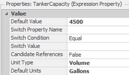
Figure 21.39: Properties of the TankerCapacity Property
21.6.3 From the [Flow Library], insert a ContanerEntity named CEntTankerTruck, which has the Initial Volume Capacity set to the TankerCapacity (i.e., a 4500-gallon tanker) as seen in Figure 21.40. Change the picture to the same tanker and resize it to be smaller. Also, you may want to make the tank square and stretch it out.
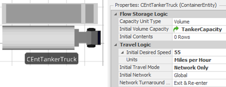
Figure 21.40: etting up the CEntTankerTruck
21.6.4 Select the Srctanker and specify the new CEntTankerTruck as the Entity Type. Since we will only have one tanker in the system, set the Maximum Arrivals to “1” under the Stopping Conditions section (see Figure 21.41).

Figure 21.41: Modifying the SrcTanker to Create One Tanker
21.6.5 Next, we will create the refill station where the tanker will be filled up and then allowed to transport the gas to the gas station, as seen in Figure 21.42.
- Disconnect the FlowSrcFill from the TankGas as we will use the tanker to fill up the tank.
- Insert a new Filler named FillTanker, which allows us to fill up a container in an entity. Also, make the processing station queue-oriented to allow the large tanker to be seen while processing.
- Connect the SrcTanker via a path to a ContainerInput node of the FillTanker.313
- Finally, Connect the FlowSrcFill to the FlowInput node of the FillTanker.
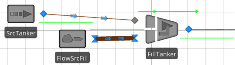
Figure 21.42: Refill Station Area
21.6.6 Once the tanker arrives at the gas station, we need to pump the gas out of the tanker and into the tank. Insert a new Emptier named EmptyTanker and connect the FlowOutput node to the TankGas via a FlowConnector, as shown in Figure 21.43. The emptier can either empty all the contents of the container entity or a specific amount. In this case, we will empty all of it until the TankGas is full (i.e., the EvntStartPumps is fired when the tank is full).
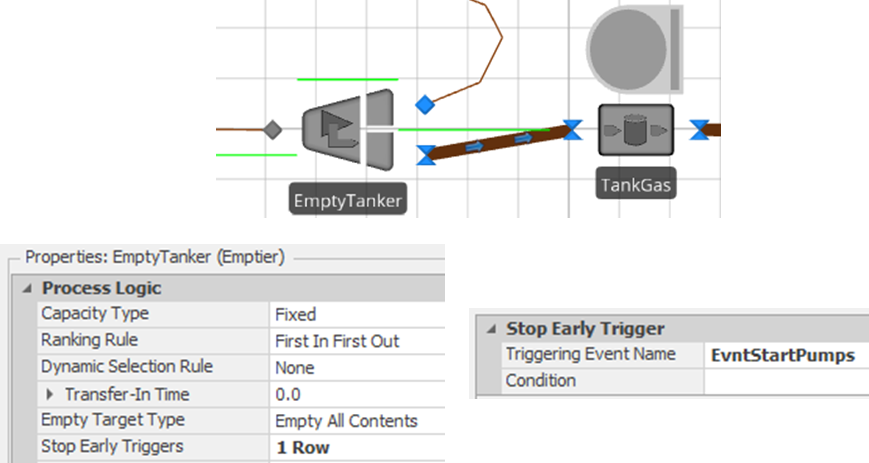
Figure 21.43: Using the Emptier to Fill up the Gas Tank from the Tanker
21.6.7 Finally connect the Output@FillTanker to the Input@EmptyTanker via a time path as well as the ContainerOutput@EmptyTanker to the ContainerInput@FillTanker. Both time paths should have a Travel Time set to Random.Uniform(3.37,4.125) hours to travel between the gas and refill station (see Figure 21.44).
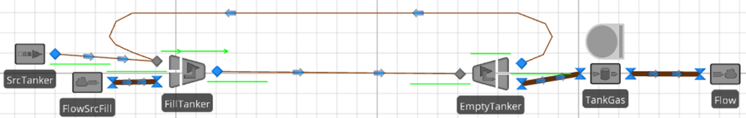
Figure 21.44: Tanker and Gas Station Refilling System
21.6.8 Save and run the model.
21.6.8.1 Are cars being allowed to get gas immediately?
_______________________________________________
21.6.9 If we want the pumps to be shut off and the cars to renege like before, in the EmptyTanker Emptier, we will need to specify the Before Processing add-on process trigger to be the Input_SnkTankerLeaves_Entered. Create a new After Processing trigger that will be used to turn the gas pumps back on, as seen in Figure 21.45.
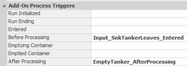
Figure 21.45: Using Process to Turn the Pumps On and Off when Filling up Tank
21.6.10 If you recall, the Input_SnkTankerLeaves_Entered process shuts off the pumps and then waits for the tank to fill up before turning them back on. The EmptyTanker object is performing the filling task now which means we need to separate the shutting down of the pumps from the starting of the pumps. For the EmptyTanker_AfterProcessing, copy the Assign step (i.e., “PumpsOnandStopFlow”), which is after the Wait step, that turns the pumps back on. You will need to delete the assignment that shuts down the FlowSrcFill output regulator since that is handled by the refilling station, as seen in Figure 21.46.
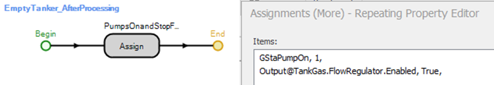
Figure 21.46: After the Tanker Finishes Emptying, Turn Pumps Back On
21.6.11 For the Input_SnkTankerLeaves_Entered, delete both the Assign and Wait process steps after the Search step, as seen in Figure 21.47.
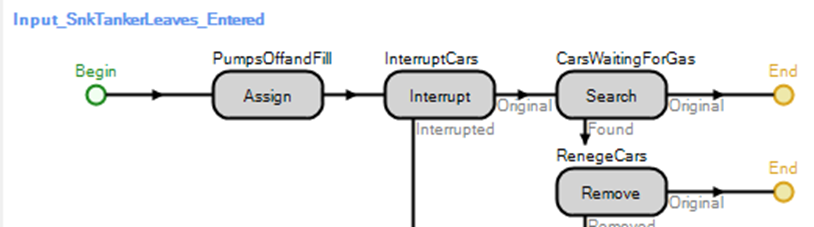
Figure 21.47: Only Shutting Down the Gas Pumps and Forcing the Cars to Renege
21.7 Commentary
- Continuous variables in SIMIO can be very useful, although the rates of change (second derivative) are limited to constants. The addition of the new flow objects has made it much easier to use these and integrate them into discrete systems.
- For our gas station, we could have combined the gas pumps with the continuous system and used the filler. Because the Filler object can fill only one item (i.e., capacity of one) at a time, you would need a Filler for each of the four gas pumps. Then, we would need to employ the concepts from Chapter 8 to restrict flow entities to the pumps (i.e., a single queue using a Resource object). Then, the cars become container entities, which, when created, would modify their gas tank size to specify the amount of gas needed. You would connect the output of the TankGas to the four gas pump fillers while removing the FlowSink.
- The uses of reneging and interruption concepts were introduced in this chapter and should not be ignored. Reneging allows entities in queues to be removed and either destroyed or transferred. Processes may also be interrupted. These features are not often used, but when they are needed, they are extremely valuable. Notice also that the modeling is accomplished through processes, not though additional specifications on the objects, as one might see in other simulation languages. This approach grants considerable flexibility to the modeler.
- The debugging facilities in SIMIO are quite extensive. When combined with animation display options, the trace, breakpoint, watch, and dashboard window can provide needed detail about the behavior of the simulation.
- The value of the “Simbits” should not be underestimated. They contain numerous examples of highly useful modeling approaches on many various topics.
This “simple tank” example is adapted from the SIMIO “SimBits” which are another way help you learn about SIMIO.↩︎
Select the Resource object and then choose the symbols from the “Symbols” tab.↩︎
This is done under the Definitions tab in the Properties section.↩︎
You can either create the process here that will respond to the Monitor event or you can create a generic process with the Triggering Event property set to the Monitor event (e.g., MonTankFull.Event).↩︎
The Execute step will run any process that has been defined.↩︎
The default unit for volume and flow rate is cubic meters and cubic meters per hour which we are converting back to gallons and gallons per hour.↩︎
Move to the 3D view and use the shift key to move the gauge up in space to place it directly on top.↩︎
You can also just delete the two Monitor elements, the three processes, the circular gauge, the ResTank and polyline from the current model rather than copying the objects over to the new model.↩︎
Note, the rate negative is positive this time because of the way the flow library works.↩︎
The regulator inside the Output@FlowSrcFill that embodies the continuous level state variables and thus the rates as was done before.↩︎
Notice we do not specify it to be negative as was done in the manual process of the previous section.↩︎
You will have to type in these state variables as they will not show up in the dropdown list of possible state variables.↩︎
The one path will allow the tanker be seen as it fills up the tank. Also, we have two sinks for the cars to automatically collect statistics on cars that balk and those do not.↩︎
You might want to make the tanker a little smaller.↩︎
Throughout this example we will use the Assign process step rather than using the State Assignments in the modeling objects. Ultimately the Assign steps offer more generality since the State Assignments are only available on entry to and exit from the object.↩︎
You may want to arrange the processing station animated queue to be oriented with four points around the server like a gas pump.↩︎
It is necessary to invoke this process after the truck leaves the output at the source so that a time in system can be computed for the truck. If this process is invoked before the truck leaves the output, then its time in system is not updated.↩︎
Note that two tokens are now active.↩︎
The simulation will warn you when you run the simulation and the entity that is entering the container input node does not have a tank associated with the entity (i.e., it is not a ContainerEntity).↩︎