Simulation Modeling with Simio - 6th Edition
Chapter
20
Creating New Objects
Traditionally, an object is created (instantiated) from an object class. The class describes an object’s composition in terms of its attributes and the methods (procedures) it performs. In SIMIO, the model itself is an object (from the Fixed Class). When SIMIO is initiated, a Model and a ModelEntity are automatically created within a new Project Library. The ModelEntity defines the DefaultEntity as part of the project, and instances of this run-time class can be created throughout the simulation run. The Model is formed by combining instances/objects from the libraries available, usually including the [Standard Library]. It is not possible in SIMIO to create utterly independent simulation objects. Models must be formed from either the base classes or by “subclassing” an existing object class. The five base classes are Fixed Class, Entity Class, Transporter Class, Node Class, and Link Class. There is a Processor class derived from the Fixed Class to help create processing objects.
When developing new objects, the user must adopt an “architect’s view” and a “user’s view” since few object classes are developed to create only a single object. Instead, new object classes, like a Server or Transfer Node in SIMIO, are expected to be used many times in one or more simulation projects. Therefore, the purpose or scope of an object’s use becomes central to its design. SIMIO object classes have been developed for many purposes and with diverse users in mind.
Consider the Server object class, which is basically designed as a single queue (input buffer) with fixed or scheduled multiple identical servers (at processing). However, it allows for many specifications, including static and dynamic ranking, transfer-in time, flexible processing time with the option of tasks, buffer capacities, material handling, reliability of servers, activity-based accounting, secondary resources, state assignments, etc. In other words, this object class is designed for a wide variety of uses. While state assignments, the acquisition of additional resources, and many of the additional features could be user-implemented in SIMIO processes, they are made “convenient” specifications for users not wanting to write processes, making the object class more accessible to casual or learning users. As you review the design of the Server, you can begin to understand the architectural “paradox.” Namely, you want your objects to be “powerful” with many features for widespread application, yet you want them to be “simple” so they can be quickly understood and used. It’s not an easy compromise. Generally, the SIMIO objects tend to favor the powerful side of the paradox, while in our development, we will tend to explore the simple side.
Object classes with many features like those in SIMIO are typically called “heavyweight” because each object requires a lot of information and has numerous procedures.288 Lightweight objects may have limited use but are easy to understand and use and, if appropriately designed, can become easy to extend through object inheritance and/or composition. This chapter will focus on creating lightweight specialized objects, objects with limited purpose (compared to SIMIO objects). However, in these creations, significant references are made to the SIMIO objects as guides for development, and the new object classes will become a part of our custom library. Also, we use the words “object” and “model” interchangeably, which SIMIO also uses.
20.1 Creating a Simple Delay Object
The previous chapter created a new delay transfer object by subclassing the standard TransferNode to delay entities that enter the node. However, the entities will queue up at the transfer node right on top of one another. Also, there is no opportunity to add a different symbol (i.e., an oven, etc.) to represent the delay location since the transfer node takes up zero space. A new fixed object (i.e., a simple delay object) will be built that only delays an entity in its path, similar to any of the standard objects. Of course, such a delay can be accomplished by an infinite capacity Server or even just a TimePath, but creating this simple delay object will be instructive both in its creation and as a base for extension.
20.1.1 Load the model from the previous chapter and save it as Chapter 20.1.spfx.
20.1.2 Insert a “New Model” icon, select the “Fixed Class” option to produce a new object class type, and name it SimpleDelay. In the “Advanced Options” properties of this object class, be sure that its Resource Object property is “False” since we don’t plan to use these objects as resources.289
20.1.3 Within this new object class, add a new expression property named DelayTime. Its Default Value is Random.Pert(1,2,4).290 The Unit Type would be Time, and the Default Units should be Minutes. Finally, specify “Process Logic” as the Category Name.
20.1.4 Objects that contain or constrain entities (Sources, Servers, Combiners, Separators, Workstations, etc.) utilize Station elements to house these entities. The Station element may be used to define a capacity-constrained location within an object where one or more visiting entity objects can reside. From the Definitions→Element, insert a new Station named StationDelay. Its Initial Capacity should be Infinity because we don’t want to restrict the number of entities using the station.
The station element has two queues associated with each station: Contents and EntryQueue. The EntryQueue is the queue where entities wait until there is available capacity to allow the entities to move into the Contents queue. Suppose you specify that the input buffer is ten for a Server, and the eleventh entity arrives at the server. In that case, the entity will be placed into the EntryQueue and not be allowed to enter the server (i.e., it will stay at the input node of the server).
Notice the Server.InputBuffer.Contents queue has already been used to determine the number of entities waiting in the input buffer to be processed or the Server.Processing.Contents are used to determine the number of entities that are currently being processed at a Server.
20.1.5 The delay Station element allows the entity to reside while it is being delayed. However, entities need a way to enter and exit the SimpleDelay. The external view creates the visual interface and provides enter and exiting nodes to the object. Go to the “External” section underneath the Definitions tab to create the visual interface.
- First, we need to define the “symbol” to represent objects from this class. You can use a symbol from the existing SIMIO symbol library, create your own using the Drawing tab, download a symbol from the Trimble 3D Warehouse, or import from several CAD programs (e.g., SketchUp © 2023). In this case, we will create a symbol using the drawing shown in Figure 20.1.
- From the Drawing section, insert an Ellipse centering it on the grid. In the Object section, change the Object Height to 0.75 and the Line Width to 0.02. From the 3D view, color the top grey and the side and line black. Make the drawing roughly two meters wide.
- Next, insert a half diamond to represent the delay. Using the Polygon tool,, just define the top, right, and bottom points. Place the shape so it is positioned halfway on the ellipse. Switch into 3-D view, select the shape, and raise the label while holding the Shift key down so that it’s barely above the ellipse. Switch back to the 2-D view to center in Figure 20.1.
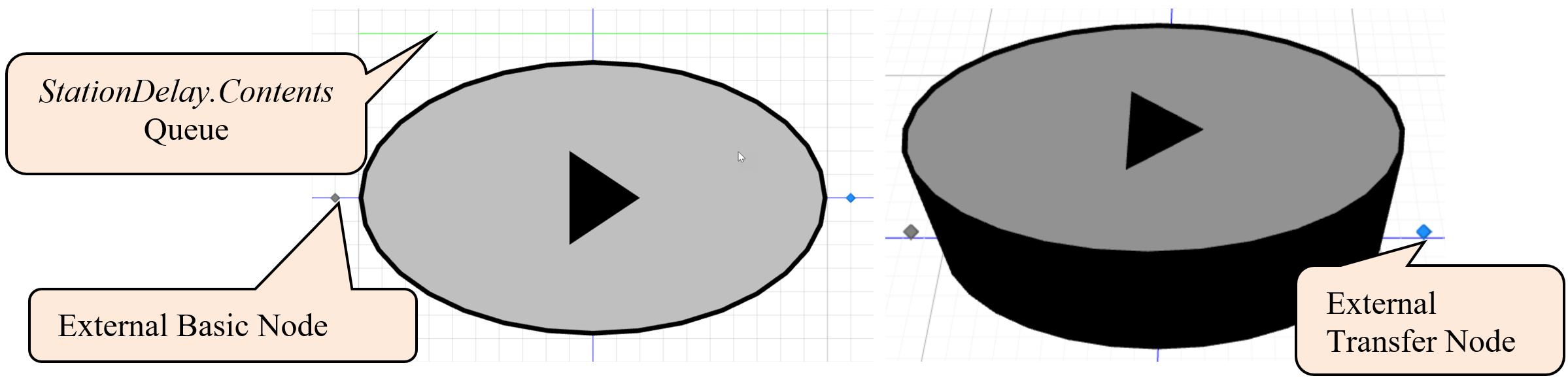
Figure 20.1: Delay Symbol
20.1.6 Add the Input and Output nodes, which provide the mechanism for objects to arrive and leave the Delay object. Click the External Node from the Drawing→Transfers section to add two external nodes and position them to the edges of the object, as seen in Figure 20.1. External nodes have specifications explained in Table 20.1 that need to be defined.
| Specification | Description |
|---|---|
| Node Class Name | The type of node this external node should be (BasicNode, TransferNode, DelayTransferNode, etc.). Transfer nodes are typically used as exit/output nodes since they contain the logic to route entities to the next destination, while basic nodes are used as entrance/input nodes. |
| Input Location Type | Location type in the object that an entity transfers into using this external node (e.g., Station, Node, or Container). If you have added objects to the facility window and want to transfer the entities to one of the nodes in the fixed model of the new object, select “Node.” |
| Station Name | Which station will the entity transfer from this node if “Station” is the input location type? |
| Node Name | Which node in the facility of the object should entities be transferred from this external node if “Node” is the Input Location Type? |
| Container Name | Which container in the object’s facility should entities be transferred from this external node if the Input Location Type is “Container.” |
- The Input node should be a BasicNode as specified in Figure 20.2. When entities enter the node, we want SIMIO to automatically transfer them to the Station StationDelay.
- The Output node will be a TransferNode to allow entities to be routed and/or ride on a transporter.
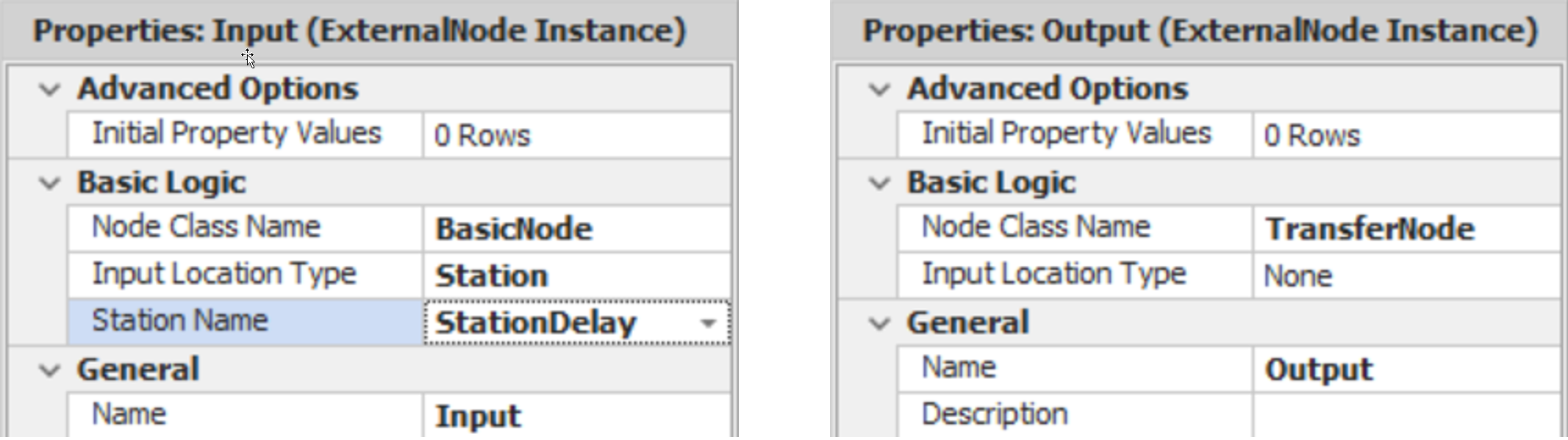
Figure 20.2: Delay Symbol
20.1.7 Unlike the DelayTransferNode, the entities are contained in the station in one of the two queues. As entities enter the delay object and are delayed, the entities can be visually seen in the queue. Insert the animated queue above the symbol by selecting the Queue under the “Animation” tab. The QueueState should be the Contents Queue of the StationDelay (i.e., StationDelay.Contents.
20.1.8 Since we have defined the default external view, the logic to process the entities entering the objects needs to be specified. Stations automatically respond to three events, as described in Table 20.2.
| Event | Description |
|---|---|
| Entered | Fired when entities leading edge enters the station |
| Exited | Fired when entities exit the station |
| CapacityChanged | Fired when the capacity of the station changes |
- Create a new process named OnEnteredDelay, which will be executed every time an entity enters the Station by specifying the Triggering Event as StationDelay.Entered as seen in Figure 20.3.
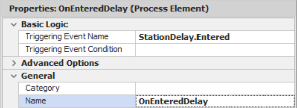
Figure 20.3: Specifying the Entered Triggering Event of the Delay Process**
- The first thing that needs to happen is that the entity has to end the transfer into the station using an End Transfer step, which indicates that the entity has finished the transfer. This step also fires the entity’s transferred event, which tells the input node that the process has been completed.
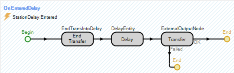
Figure 20.4: Station Activity
- Next, add a Delay step similar to before (see Chapter 19) specifying the DelayTime as a referenced property.
- Once the entity has been delayed, it needs to be transferred out of the SimpleDelay using a Transfer step as specified in Figure 20.5. Notice the entity is sent to the external output node to enter back into the parent model when it leaves the new object:
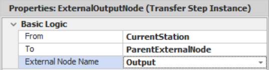
Figure 20.5: Transfer Step Specifications
20.1.9 Next, we need to use the new DelayObject in our model, as seen in Figure 20.6. Switch back to the main create Model (within the Navigation window). We will insert the delay between two nodes to facilitate multiple changes as we modify the object to avoid setting the paths each time.
- Delete the TimePath connecting the TNormal to the SnkExit. Insert a new TransferNode and connect it to the SnkExit via a ten minute TimePath. Also, you will need to specify the SetTimeClock as the Entered add-on process trigger.
- Insert a SimpleDelay object from the [Project Library] and call it DelOperation. Specify the delay time to be four minutes to match the TDelay time. Use connectors to link the input and output nodes.
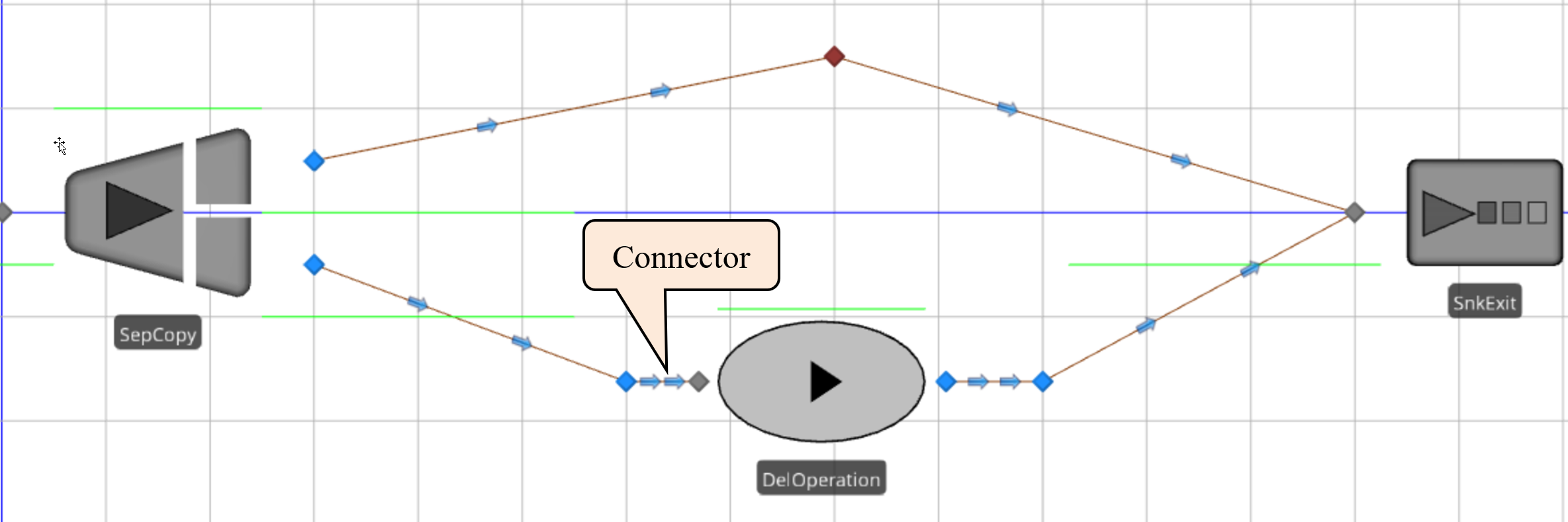
Figure 20.6: SIMO Model with Simple Delay
20.1.10 Save and run the model for 24 hours, observing the differences between the delay object and the delay transfer node. Set the arrival rate to two minutes to see the differences. Note, if your entities are upside down in the queue, then the animated queue in the “External” view was drawn in the wrong direction (i.e., it should be right to left).
20.2 Adding Color and Processing Contents
One of the features of the SIMIO objects (e.g., Server)is they change color based on their status (state). With some work, we can mimic this behavior in our delay object, so it turns a different color when entities are being delayed versus when the delay object is idle.
20.2.1 The Server keeps track of its states using a List State variable named “ResourceState.” The List State variable defines a discrete integer variable with a list of possible values from zero to N. You need first to define a string list with the names. Select the SimpleDelay in the Navigation panel. From the Definitions→Lists, insert a new string list named LstDelayStateNames with “Idle” and “Delaying” as the two potential states.
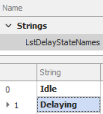
Figure 20.7: Specifying the Names of the Potential States
20.2.2 Insert a new List State variable named StaDelayState, which uses the LstDelayStateNames list. Since SIMIO will automatically track statistics on each state, specify the Data Source and Category property as seen in Figure 20.8.

Figure 20.8: Setting up the List State Variable.
20.2.3 Once the entity enters the delay station, the delay state will be “Delaying” and will potentially become idle when it leaves the simple delay object, as seen in Figure 20.9.
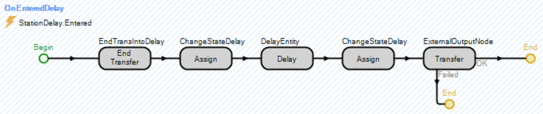
Figure 20.9: Modifying the OnEnteredDelay to Change the Delay State
- Insert an Assign step that sets the StaDelayState to “1” immediately after the End Transfer.
- Right before the entity leaves (i.e., the Transfer step), we need to update the status to idle if this is the only entity in the delay station. Insert another Assign step that sets the StaDelayState variable to StationDelay.Contents.NumberWaiting>1, which will evaluate to zero if this is the last entity in the delay station or one, as seen in Figure 20.10.
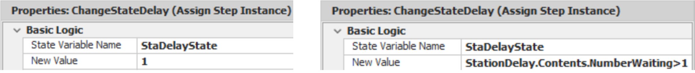
Figure 20.10: Changing the State of the SimpleDelay Object
20.2.5 Save and run the model for 24 hours, looking at the results.
20.2.6 Currently, only one symbol is defined. To add additional symbols to our simple delay, click first on the “External View” for the SimpleDelay object and select the Additional Symbols tab. Now add an additional symbol and color the ellipse of the new one “green” (i.e., the green color will represent the status “Delaying,” meaning there are entities in the delay). See the symbols in Figure 20.11.
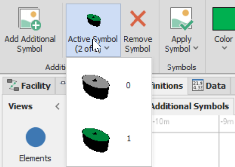
Figure 20.11: Symbols for the Two States Idle and Delaying
20.2.7 To use the states to define which symbol to display, change the Default Current Symbol Index in the Properties window to the SimpleDelay.StaDelayState.
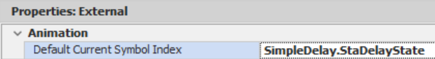
Figure 20.12: Using the Delay State to Change the Symbol
20.2.8 Return to the primary Model and delete the current DelOpeation from your SIMIO model since the external view has not been updated with instances that have already been defined. Insert a new SimpleDelay and set the delay time to “4” minutes. Save and run the model.
20.2.9 Does it change color when entities occupy the delay?291
_______________________________________________
20.3 Embellishing with User-Defined Add-on Process Triggers
Perhaps the greatest flexibility you can add to your objects is to allow users to add on processes that change the object’s behavior to meet their needs. This addition assumes that your user knows how to create those processes. Many of the SIMIO standard objects allow the user to augment the processing of an object via add-on process triggers (e.g., Run Initialized, Entered, Exited, Processing, Processed, etc.). These user-defined add-on process triggers must be specified to allow our new object to mimic the standard objects.
20.3.2 Insert a Process Element Reference property for the “Run Initialized” with the following properties. Like the other objects, this process will run at the start of a simulation. New category names can be created by just typing in the category into the entry box.
| Property | Value |
|---|---|
| Name | RunInitializedAddOnProcess |
| Description | Executes when the simulation run is initialized. |
| Required Value | FALSE |
| Display Name | Run Initialized |
| Category Name | Add-on Process Triggers |
| Default Value | Empty String |
- Add the “Entered” Process Element Reference property with the following properties that will be executed as soon as an object enters the SimpleDelay.
| Property | Value |
|---|---|
| Name | EnteredAddOnProcess |
| Description | Occurs immediately after an entity has entered this object and before the delay. |
| Required Value | FALSE |
| Display Name | Entered |
| Category Name | Add-on Process Triggers |
| Default Value | Empty String |
- Add the “Exited” Process Element Reference property with the following properties that will be executed once an object leaves the SimpleDelay.
| Property | Value |
|---|---|
| Name | ExitedAddOnProcess |
| Display Name | Exited |
| Description | Occurs immediately after an entity has exited this object. |
| Category Name | Add-on Process Triggers |
| Required Value | FALSE |
| Default Value | Empty String |
- Add the “Before Delaying” Process Element Reference property that will run immediately before the Entity starts the delay process, similar to the Server’s Before Processing trigger.
| Property | Value |
|---|---|
| Name | BeforeDelayingAddOnProcess |
| Display Name | Before Delaying |
| Description | Occurs immediately before an entity is to be delayed. |
| Category Name | Add-on Process Triggers |
| Required Value | FALSE |
| Default Value | Empty String |
- Finally, insert the “After Delaying” Process Element Reference property that will run once the Entity has finished delaying, similar to the Server’s After Processing trigger.
| Property | Value |
|---|---|
| Name | AfterDelayingAddOnProcess |
| Display Name | After Delaying |
| Description | Occurs immediately after an entity has been delayed |
| Category Name | Add-on Process Triggers |
| Required Value | FALSE |
| Default Value | Empty String |
20.3.3 Return to the Processes tab and insert an Execute step into the OnEnteredDelay process, which allows processes to be executed, as seen in Figure 20.13. Specify the process to be the referenced property (EnteredAddOnProcess. The Token Wait Action property should be “WaitUntilProcessCompleted” under the Advanced Options, which forces the token to wait until the add-on process has completed running before it continues to the next step.

Figure 20.13: Specifying the Entered and Delayed Add-on Process Trigger
20.3.4 Before the Delay step (see Figure 20.13) in the OnEnteredDelay process, insert another Execute step to run the process associated with the BeforeDelayingAddOnProcess trigger with the same (default) Action property value.
20.3.5 After the Delay step, insert another Execute step that will run the process associated with the AfterDelayingAddOnProcess trigger with the same (default) Action property value.
20.3.6 Add the OnRunInitialized Process, which is automatically defined for all Fixed Class objects by selecting it in the “Select Process” dropdown box. Insert an Execute step into the

Figure 20.14: Using a Built-in Process for all Fixed Objects
20.3.7 Create a new Process named OnExited and specify the TriggeringEvent property as the StationDelay.Exited event. Again, insert an Execute step to execute the process for the user-defined ExitedAddOnProcess property.
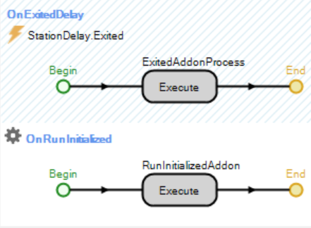
Figure 20.15: Adding an OnRunInitialized and OnExited Process
20.3.8 Let’s utilize our new add-on process triggers as a “user” of our object to allow the delay time to vary for each entity (i.e., 25% of the time, it will be four minutes, 25% of the time it will be six minutes, and 50% of the time it will be eight minutes).
- Insert a new ModelEntity real-valued state variable named EStaDelayTime whose Unit Type is Time, which will store the delay time.
- Specify the Delay Time of the DelOperation to be ModelEntity.EStaDelayTime.
- Navigate back to the Model and create a new Entered Add-on Process trigger for the DelOperation, as seen in Figure 20.16.
- Add an Assign step that assigns ModelEntity.EStaDelayTime a value from a Random.Discrete(4, 0.25, 6, 0.5, 8, 1.0) minutes.

Figure 20.16: Assigning a Delay Time for Each Entity
20.4 Embellishing with State Assignments
The SIMIO standard objects have state assignments that can be performed without the use of processes. This addition is considered a “convenience” to the user, especially since assignments are easily implemented in processes. Nonetheless, similar state assignments can be added to the new SimpleDelay to illustrate how to add this capability. Recall that an Assign step may consist of several assignments. As a result, this addition must accommodate repeating specifications.
20.4.1 State assignments are specified by a “repeating group property” because the number of assignments can vary. Add a Repeat Group property named AssignmentsOnEntering in the SimpleDelay object with the properties specified in Figure 20.17. Again, type in the new category name State Assignments so it will be similar to the other standard objects.

Figure 20.17: Adding a Repeating Group Property
The repeat group allows you to specify multiple rows (i.e., repeating) of a set of properties (i.e., the state variable and the value expression).
20.4.2 To create the properties that are to be repeated (i.e., grouped), first select the Assignments OnEntering group property, and then insert a new State Standard Property named AssignmentsOnEnteringStateVariableName since a state variable is used in an assignment with the properties specified in Figure 20.18.
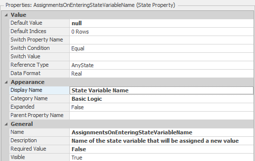
Figure 20.18: Specifying a State Variable Property
20.4.3 Next, insert the expression property that will specify the new value to be assigned to the state variable. Again, select the AssignmentsOnEntering group property first, and then insert a new Expression Standard Property named AssignmentsOnEnteringNewValue with the properties specified in Figure 20.19. Note the specification of the Unit Type carefully so units of the value can be specified based on the state variable.
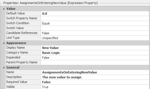
Figure 20.19: Specifying the Expression Value Property of the Repeating Group
20.4.4 Repeat the process for another Repeat Group Property named AssignmentsBeforeExiting, as seen in Figure 20.20, which shows all the properties. Notice how the group properties have their own separate properties section. You can copy the AssignmentsOnEntering and just change the name.
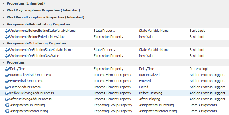
Figure 20.20: Properties Associated with the SimpleDelay
20.4.5 Once the Repeating Group properties have been defined, they can be used in Assign steps. Insert two Assign steps, as seen in Figure 20.21, before the “OnEntering” and “BeforeExiting” state assignments. One Assign step should be inserted before the execution of the entered add-on process and the other one should be inserted before the entity is transferred out of the node. Figure 20.21 shows how the reference properties are used to specify the Before Exiting Assignments property repeating group.

Figure 20.21: Adding the Assign Process Steps for the Assignment States
20.4.6 For each of the Assignments (More) properties, the state variable and new value properties must be be associated with the reference properties as well. Bring up the Repeating Property Editor by clicking the more button  , as seen in Figure 20.22.
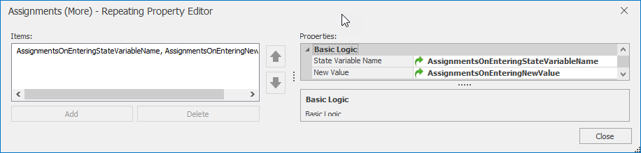
Figure 20.22: Setting up the State Variables and New Values to the Referenced Properties
20.4.7 For both the State Variable Name and New Valu properties, set the reference property to the top property for each property. Figure 20.23 shows selecting the State Variable Name referenced property.
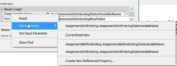
Figure 20.23: Select the Top Reference Property for the State Variable Name
20.4.8 Let’s utilize our new processes and assignments by specifying the delay time of each of the entities using the OnEntering State Assignments.
- First, remove the Entered Add-on process trigger by resetting it (reset or Null) so the add-on process will not specify the delay time.
- Repeat the same assignment as was done in Figure 20.24 using the AssignmentsOnEntering State Assignments. Assign the ModelEntity.EStaDelayTime a value from a Random.Discrete(4, 0.25, 6, 0.5, 8, 1.0) minutes.292
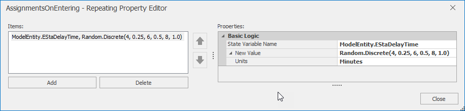
Figure 20.24: Using the State Assignments Property
20.5 Adding Secondary Resources
While it is contrary to the purpose of a simple delay object, let’s add the ability to have secondary resources, which could also be done via the add-on process triggers. We would require resources before the delay occurs and then release them right after the delay. Again, a Repeat Group property similar to the assignments must be utilized since the Seize and Release steps within the secondary resources can request/release more than one type of capacity.
20.5.1 Recall the assignments had just two properties (i.e., the state variable and the value) associated with the Repeat Group. That is not the case for the Seize and Release steps, which have many properties. The easiest way is to sub-class the Server object and then copy and paste the secondary resources (e.g., SecondaryResourcesSeizesBeforeProcessing and SecondaryResourcesReleasesAfterProcessing) into the SimpleDelay. Therefore, sub-class the Server by right-clicking to create a MyServer and then expand the Properties (Inherited) section.
20.5.2 Select the MyServer from the [Navigation] window. Under the Definitions→Properties section, expand the Properties(Inherited). Copy individually the three properties associated with SecondaryResourceSeizesBeforeProcessing, SecondaryResourceSeizesBeforeProcessingMustSimulat-aneouslySeize, and SecondaryResourceSeizesBeforeProcessingImmediatelyTrySeize, as seen in the red box in Figure 20.25. Then, paste this Repeat Group property and the two boolean properties into the CapacityDelay properties.
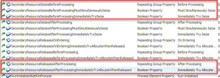
Figure 20.25: Copying the Before-Processing Seize and After-Processing Release Properties
20.5.3 Repeat the process for the SecondaryResourceReleasesAfterProcessing Repeat Group property and the SecondaryResourceReleasesAfterProcessingImmediatelyTryAllocateWhenReleased Boolean property seen in the red box of Figure 20.25 and in the SimpleDelay properties of Figure 20.26.
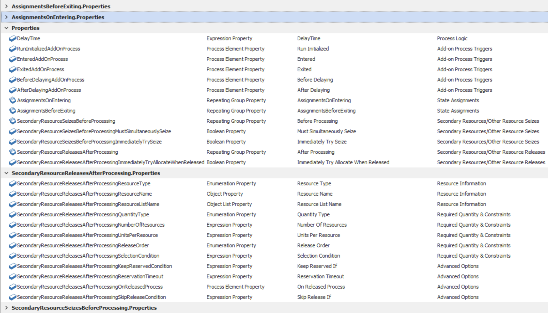
Figure 20.26: Repeat Group Properties for Allowing Secondary Resources
20.5.4 From the OnEnteredProcessing process (see Figure 20.27) inside the MyServer object, copy the Seize and Release steps before and after the process.
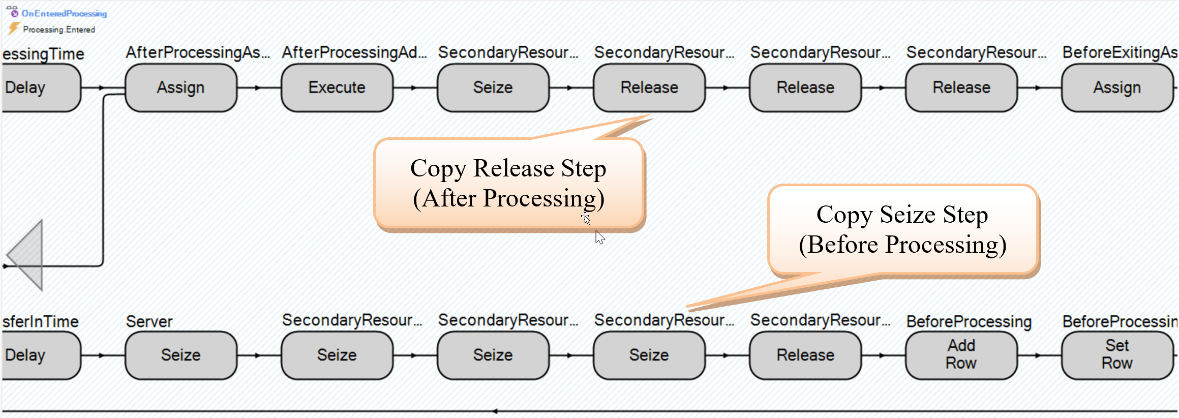
Figure 20.27: Copy Seize and Release Steps from the MyServer’s OnEnteredProcessing Process
20.5.5 Now, for into the OnEnteredDelay process of the SimpleDelay object, add the first seize secondary resources before the delay and then release them right after the delay, as seen in Figure 20.28.
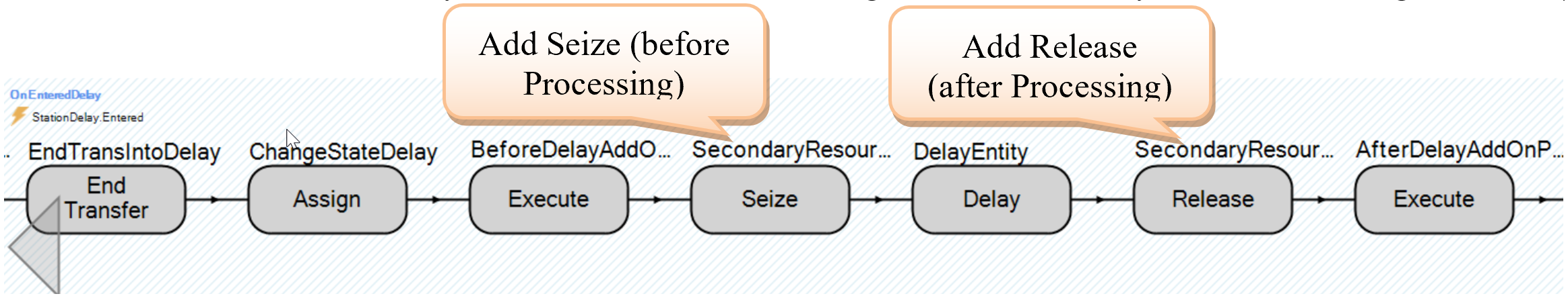
Figure 20.28: Adding the Seize and Release Steps into the OnEnteredP
20.5.6 Return to the Model and insert a Resource named ResService with a capacity of two, which is required before the delay can occur.
20.5.8 In the Secondary Resources of the DelOperation, seize the ResService in the Other Resource Seizes→Before Processing and release it in the Other Resource Releases→After Processing.
20.6 Using Storages to Distinguish Waiting versus Delaying
The processing queue for the delay station now includes waiting for secondary resources and the actual delay, so its holding time increases. Since the delay station currently has an infinite capacity, all the entities are shown in the processing animated queue even though they are not delayed. The Server object utilizes two stations (i.e., InputBuffer and Processing) to decouple the waiting and processing times. Another approach is to utilize Storage elements, which automatically calculate statistics used in the DMV problem in Chapter 8.
20.6.1 Select the SimpleDelay from the [Navigation] panel. From the Definitions→ Elements section, insert two Storage elements named StorageWait and StorageDelay, as in Figure 20.29.
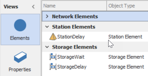
Figure 20.29: Adding Two Storage Elements to Keep Track of Waiting and Delaying
20.6.2 To calculate how long entities waited for secondary resources, we need to insert them into the StorageWait before we seize the resources and then remove them after the resources have been seized. We repeat the process to keep track of the actual delay time by inserting the entities into the StorageDelay right before the delay and removing them right after the delay, as seen in Figure 20.30.
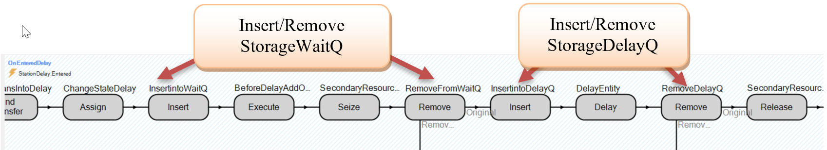
Figure 20.30: Adding the Delay and Wait Queues to the External View
20.6.3 Finally, modify the SimpleDelay object “External” view. Insert a new animated queue that references StorageWait.Queue while the processing queue should reference the StorageDelay.Queue.
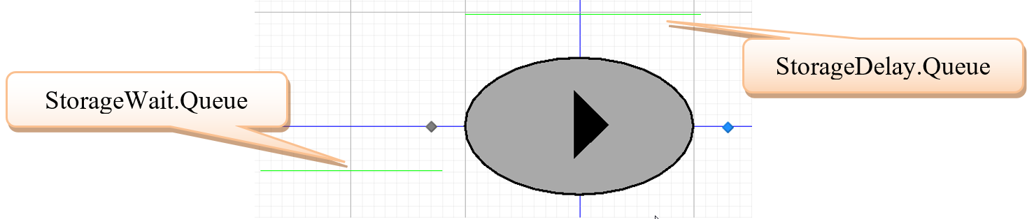
Figure 20.31: Adding the Delay and Wait Queues to the External View
20.6.4 Save and run the Main model for 100 hours.
20.6.4.1 When you switch back to the Main model, are the two new queues visible?
_______________________________________________
20.6.5 At this point, we have replicated a lot of the Server object, which is a complex object (i.e., a heavyweight/bloated object) versus our SimpleDelay (i.e., lightweight) object. Therefore, we will check our current delay with that of the Server, as seen in Figure 20.32.
- Delete TDelay (i.e., DelayTransferNode) and insert a Server named SrvComparison, which is connected via connectors from the Output@SrcParts and ParentOutput@SepCopy and to the SnkExit. Set the Processing Time property to ModelEntity.EStaDelayTime and Initial Capacity to “Infinity.”
- Delete the current DelOperation and insert another `SimpleDelay to get the new external view (i.e., queues). Set the Delay Time property to ModelEntity.EStaDelayTime. Use connectors to connect it to the two nodes as well as directly from the Output@SrcParts.
- Remove the SetTime add-on process trigger from the TNormal.
- Change the two TimePaths that leave the MemberOutput@SepCopy and the one connecting to the SnkExit to Connectors.
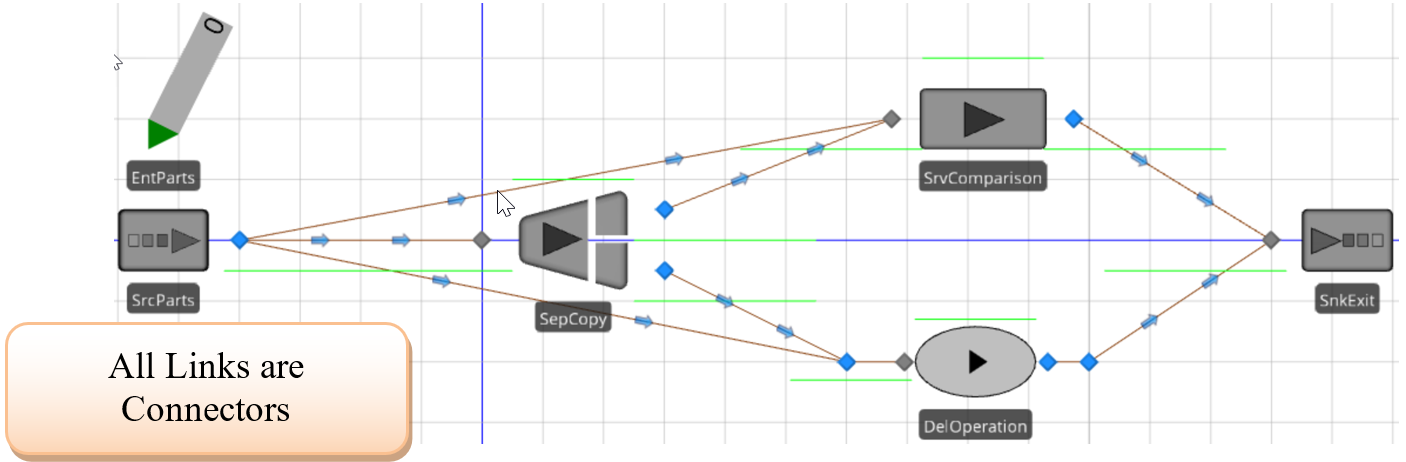
Figure 20.32: Moel to Compare SimpleDelay and the SrvComparison
20.6.6 For the DelOperation_Entered process, change the Assign step to set the entity’s delay time to Random.Pert(1,2,4,1).293
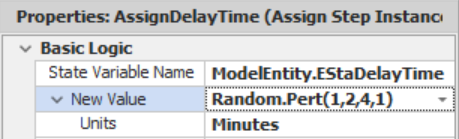
Figure 20.33: Changing the Delay time of the ModelEntity
20.6.7 Next, for the SrcParts, specify the DelOperation_Entered as the Created Entity add-on process trigger and change the arrival Interarrival Time to Random.Exponential(3,2).
20.6.8 To facilitate comparing the two systems (i.e., the server versus the simple delay) in an experiment, we will route the entities either to the SrvComparison or to the DelOperation. Select the Output@SrcParts, change the Entity Destination Type to “Specific,” and then right-click on the Node Name to create a new reference property, as seen in Figure 20.34.
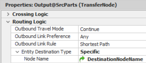
Figure 20.34: Setting up the Output Node for Experimentation
20.6.9 Create a SIMIO experiment where we will specify the Destination Nodeas the only control.
- Set the run length to 5000 hours. Also, specify that you only want “1” replication.
- Specify the Input@DelOperation as the DestinationNodeName and run the one replication observing the actual run time.
- Reset the experiment, change the DestinationNodeName to Input@SrvComparison, and rerun it.
20.6.9.1 What did you get for the execution time for each of the experiments? Do you think the difference is important?
_______________________________________________
20.6.10 Now let us compare the two systems, but first, we need to add secondary resources to both objects, which we will do via add-on process triggers to force some waiting to occur.
- Create a new process named SeizeService that utilizes a Seize step to acquire the ResService.
- Create a new process named ReleaseService that will release the ResService.
- Specify the SeizeService as the add-on process trigger for Before Processing for the SrvComparison and the Before Delaying for the DelOperation.
- Finally, specify the ReleaseService as the add-on process trigger for After Processing for the SrvComparison and the After Delaying for the DelOperation.
20.6.11 From the Experiment window, set up two scenarios that specify Input@DelOperation and Input@SrvComparison, respectively, with 100 replications. Change the run length back to 100 hours.
20.7 Considering Capacity Like a Server
At this point, we have added the ability to have secondary resources to constrain the capacity of the delay. Adding capacity to our delay object adds new considerations because entities cannot enter a delay when the delay object is at capacity.
20.7.1 Select the SimpleDelay object and access the properties. Rename our SimpleDelay object.294 to CapacityDelay and change the Resource Object property in the “Advanced Options” to “True.” We will use the capacity specifications that are a consequence of making this a resource object (note the “additions” to the “Process Logic” category).
20.7.2 The Fixed Object now provides the ability to change the capacity. However, the StationDelay station is the location that actually constrains the entities. Therefore, from the Definitions→Elements, specify the properties in Figure 20.35 to link the CapacityDelay properties, which are visible to the modeler, to the internal Station’s properties.

Figure 20.35: Linking the Station Capacity to the CapacityDelay
20.7.3 The OnEnteredDelay process can now be modified, as shown in Figure 20.36.
- Insert a Seize step after the secondary resources seize. To seize capacity from the object, specify ParentObject as the Object Type within the Seize step, as seen in Figure 20.37.
- Since the object is constraining the entities, we will move the Assign that changes the state to delaying after the Seize of the CapacityDelay object.
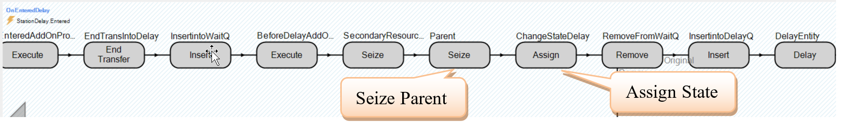
Figure 20.36: OnEnteredDelay CapacityDelay
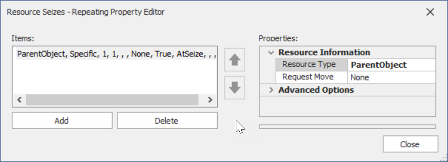
Figure 20.37: Seizing the Parent Object
20.7.4 To release the object, insert a Release step into the OnExitedDelay using the same object type as in the Seize step.
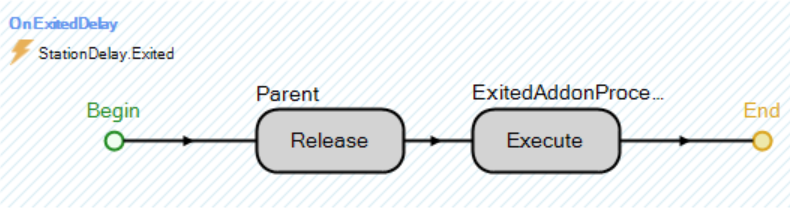
Figure 20.38: Releasing the CapacityDelay Object in OnExitedDelay
20.7.5 In the Model, set the Initial Capacity property to “2” for both the SrvComparison and the DelOperation. Also, remove all the add-on process triggers for both objects.
20.7.6 Save and run the experiment.
20.7.6.1 What is the average and half-width of total time in the system and the time waiting for the two scenarios (compared to the previous section)?
_______________________________________________
20.7.6.2 What is the average time (in minutes) spent waiting in the DelOperation Entry Queue?
_______________________________________________
20.7.7 You will also notice that the utilization of each object’s resource is the same, and the state utilization of the Server versus the CapacityDelay (i.e., Starving versus Idle and Processing versus Delaying). To fix the issue of not seeing the entities waiting, we can change the animated queue that is set to the StorageWait.Queue or add an additional animated queue that sets as the Queue State property to DelayStation.EntryQueue. Note, if we added an additional queue, we could distinguish among waiting for the actual object (i.e., Entry queue statistics) versus waiting for secondary resources (i.e., StorageWait queue statistics).
20.8 Commentary
- Creating your own specialized objects can really enhance your models, which is one of the important advantages of using SIMIO. However, if you are only going to use the object once in one particular model, it may not make sense to spend time creating a specialized object that could be handled in processes. The advantage is that it can be reused within the same model or different models.
- Instead of the need for capacity at the station (location), consider the capacity restriction of the object to be a separate concern from the resources needed. It greatly simplified the object, especially in contrast to the SIMIO server.
- However, as we developed the object, we realized there was a strong interest in adding “features,” and the appropriate stopping point was unclear.
The Vehicle/Worker is clearly the most complicated of the SIMIO standard object classes.↩︎
Most SIMIO object are resource bound and have capacity.↩︎
Since the expression editor is not active, type the expression directly into the Default Value. We will tend to use the random number stream specification throughout to aid comparisons.↩︎
Note, the user has the ability change the Current Symbol Index in the model just like any other standard SIMIO object.↩︎
If the Units do not show, then the New Value property was not setup correctly (see Figure 20.19).↩︎
Note we are using the fourth parameter which specifies the random stream so we induce as much correlation into comparing scenarios.↩︎
You could have sub-classed the SimpleDelay to be the CapacityDelay.↩︎
20.6.4.4 Comment on the simplicity and transparency of this object.
_______________________________________________