Simulation Modeling with Simio - 6th Edition
Chapter
7
Using SIMIO Processes
Most simulation languages hide the details of executing the processes associated with an event. Generally, SIMIO has taken care of performing these steps, and we have been somewhat ignorant of what specifically happens unless you have looked at the trace. Also, it is usually difficult to look “under the covers” in most simulation languages and add your own features to the simulation model.
An innovative feature of SIMIO is the capability to modify an object’s behavior through the use of SIMIO “Processes.” In essence, you can determine some new things that will happen based on current conditions. SIMIO processes offer a wide range of modeling opportunities, which will be employed in this and later chapters. Processes are very flexible and can model many varied behaviors beyond those intrinsic to the object (such as a Server). Processes allow you to extend and expand the modeling capability of native SIMIO. There are two basic considerations when using and developing processes.
- “When” is the process invoked or executed?
- “How” do you write a process to produce the desired behavior?
By now, you realize that a simulation is executed by moving from event to event. SIMIO has defined certain events from which you can respond with a process to change the model behavior. Processes are a sequence of simulation “steps” typically invoked by actions of objects within the simulation or by events whose response you write. Writing a process is similar to creating a stylized programming flowchart, except that the components of the flowchart are logical simulation “steps” such as Assign, Decide, Tally, Transfer, Seize, Delay, Release, and so forth. The actual execution of the process is performed by a “token.” The Token is a SIMIO object that can have state variables, but it is not the same as an entity. The tokens execute the steps of a process on behalf of an object, typically the object whose behavior is being modified by the process or where the process resides (i.e., Parent Object) or the object causing the modification (i.e., Associated Object). The relationship among the token, objects, and process is shown in 7.1.
7.1 The Add-On Process
We will initially focus on the SIMIO “Add-on Process” triggers. These are events triggered by actions of objects but mostly by entities to change the behavior or cause an action for an object that is needed for your particular model. In the case of an Add-on process, the Parent Object is primarily the main Model since the Add-on processes are created within the main Model and are viewed and edited in the “Processes” tab of the Model. Often, the Associated Object is the ModelEntity that triggers the particular process to be executed.
7.1 shows an example of the “Entered” Add-on process trigger. When Entity30 enters the SrvPacker1 server, the SrvPacker1_Entered process is triggered. At this point, a Token associated with Entity30 is created at the Begin endpoint and travels step to step in zero time (e.g., the Token is currently at the beginning, getting ready to execute the Assign step) until it reaches the End endpoint at which time it is destroyed. In this example, the Associated Object is Entity30, and the Parent Object is the main Model. The Token is executing the steps on behalf of Entity30.75

Figure 7.1: Example Explaining Entity Triggering an Add-on Process
7.2 The Add-On Process Triggers: Illustrating “Assign” Step
Almost all SIMIO objects have “Add-On Process Triggers.” These triggers cause external processes to be invoked as part of other processes. So, as a part of the execution of the object, arbitrary “processes” of your design can also be executed, which helps change/expand the underlying object’s behavior (i.e., Server) without having to look inside the object, which will be explored in a later chapter.
In Chapter 6, the characteristics of the entities were changed. In one case, the entity types (i.e., the memory chips) were colored, and in the second case, the memory board entity’s height was changed. In both cases, we used “state variables” whose values were changed using the “State Assignments” properties of the Source and Server objects. You will see that there are only a few opportunities within an object to make state assignments, while there are many more Add-On Process Triggers. Furthermore, the “State Assignments” can only assign state variable values, whereas a process can incorporate more logic than just simple assignments.
7.2.1 Let’s see how to replicate the “State Assignments” using Add-On Process Triggers. Bring up the model from the prior chapter. First, remove the “State Assignment” from the SrcMemoryChip Source by deleting it within the Repeating Property Editor.
7.2.3 Choose the “Exited” Add-On Process trigger. Double-clicking on this trigger automatically creates a new process named SrcMemoryChip_Exited, which then selects the “Processes” tab. You will see a “flowchart” with a “Begin” and an “End,” as seen in 7.2. By clicking on one of the process Steps, you can insert it into the flowchart, which will adjust itself automatically.
7.2.4 Insert an Assign step as shown in 7.2.

Figure 7.2: Inserting the Assign Step
7.2.5 Under the properties window, you will see a place to put the State Variable Name and its New Value. You can only assign one state variable. However, you can also invoke the Repeating property Editor by clicking beside the “Assignments (More).” Add the following two assignments using the latter approach, as seen in 7.3.76 It should look very familiar as the “State Assignments” utilize an Assign step internally.77
State Variable Name: ModelEntity.EStaChipType
New Value: Random.Discrete(1, 0.5, 2, 1.0)
State Variable Name: ModelEntity.Picture
New Value: ModelEntity.EStaChipType-1
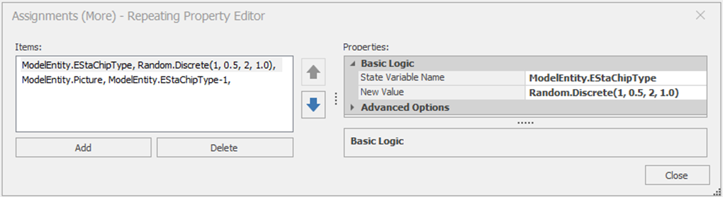
Figure 7.3: Repeating Property Editor for Assignment Process Step
7.2.6 Recall from the previous chapter, we calculated statistics on the efficiency of packer one. The efficiency was used to change the processing time of the packer based on the number in the queue. The state variable was updated when the entity entered the packer, including the current entity, rather than when the entity entered processing, where the efficiency value is used. The reason for not calculating the statistic correctly is there are only two default places for assignments (i.e., entering or exiting the server), but processes allow more flexibility. To fix the issue, delete the state assignment from the “On Entering” at SrvPacker1. Create a “Processing” Add-On Process Trigger which will calculate the efficiency right before the processing starts. Insert an Assign process step that does the following – see 7.4.78
State Variable Name: GStaPacker1Efficiency
New Value: FuncEfficiency
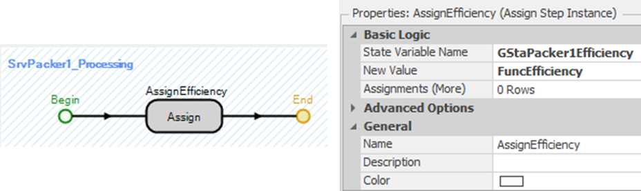
Figure 7.4: Recreating State Efficiency Assignments
7.3 Creating an Independent “Reusable” Process
Creating a “generic” process that can be used in several places within a model is useful. In the model from the prior chapter, the assignment to change the height of the board to make the entity look like a package was done at each packer station. Of course, this approach could be duplicated by creating an “Exited” add-on process trigger for each packer. However, the same exact logic of assigning the height has to go in each of the three “Exited” add-on process triggers. Instead, let’s create a “common” process that we can refer to for each packer rather than creating the same one for each packer. This type of process is called a “reusable” process and allows for modification in one place rather than three.
7.3.3 For each of the packer object’s “Exited” Add-On Process Trigger, instead of creating a new one; just select the Packaged process from the drop-down list. Again, select all three packers to change them all at once, as seen in 7.5.
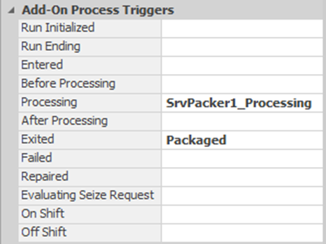
Figure 7.5: Utilizing a Common Process in all Three Packers
7.4 Collecting Tally Statistics
Recall that observation-based statistics are referred to as Tally statistics in SIMIO. These statistics are gathered as observations as the simulation executes. Examples would be queuing times, flow times, cycle times, and time in system. For the most part, these are statistics whose observations are intervals of time. Previously, Tally statistics collection was limited to BasicNodes, TransferNodes, or the default results. Now, we want to greatly broaden the possible collection points, namely in any process.
7.4.1 Let’s consider collecting Tally statistics on the time boards, and chips spend in the system, from arrival time to the time they start to be packed at Packer1 only. To accomplish this addition, we need to first define a new “Element.”79 When working with Tally statistics, we define them before determining their collection method. Under the “Definitions→Elements” section, click on “Tally Statistic” in the ribbon to insert a new statistic named TallySystemTimePacker1, as seen in 7.6.
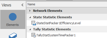
Figure 7.6: Specifying a new Tally Statistic in the Elements Section
7.4.3 Next, we need to define the collection process (i.e., logging each observation). This is done by inserting a Tally step into the SrvPacker1_Processing add-on process trigger, as seen in 7.7.
Tally Statistic Name: TallyStatSystemTimePacker1
Value Type: Expression
Value: TimeNow-ModelEntity.TimeCreated80
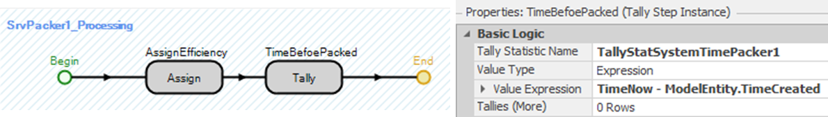
Figure 7.7: Using a Tally Step to Track Time before Packing Station 1
7.4.5 Suppose now we want only the time in system for assemblies as they start to be packed at SrvPacker1 after the first four hours of the simulation? We need to modify our process so only observations of boards are collected after the first four hours.
7.4.6 Modify our “SrvPacker1_Processing” add-on process by adding a Decide step before the Tally, as shown in 7.8. The Decide step is similar to an If statement in Excel, where when the condition is true, the process (i.e., Token) will continue via the”True” branch; otherwise, it will follow the “False” branch. The Decide Type property should be “ConditionBased” with the Expression property set to TimeNow > 4.

Figure 7.8: Adding a Decide Step
7.4.8 It is also possible to use process steps to replace the modeling changes we made to the original model in order to produce time in system statistics for each chip type (i.e., red and green) and board. The previous approach placed additional objects (i.e., Sinks) in the model, which were not part of the real system and might confuse management (or anyone else) when looking at the model.
- First, insert the original SnkExit (Sink).
- Delete all the additions (i.e., the Separator and the three Sinks) when the original SnkExit sink was replaced.81
- Next, connect the three packing stations back to the sink as before, making sure to specify the TimeToExit property as the Travel Time.
7.4.9 Next, let’s define three new Tally Statistics (remember these are “Elements”) named TallyStatBoardTimeInSystem, TallyStatType1TimeInSystem, and TallyStatType2TimeInSystem. Change the Unit Type to Time. To make these easier to find in the output, under “Results Classification,” set the “Category” to FlowTime and the “Data Item” to TimeInSystem, as seen in 7.9.
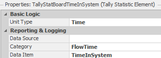
Figure 7.9: Specifying Time In System Tally Statistics
7.4.10 We will now create an Add-On Process in the Sink using the “Destroying Entity” add-on process trigger. This process is called SnkExit_DestroyingEntity and its process is shown in 7.10.82

Figure 7.10: Destroying Entity Process (Tallying Statistics)
Note the UnBatch step comes from the “All Steps (A-Z)” category in the steps panel. The UnBatch works much like the Separator object, except it breaks up the parent and the members separately in the batch and sends them along the correct branches of the step.83 Here, two tokens are active on behalf of the same associated object: one token executes on behalf of the parent, and the second token executes on behalf of the member84.
- The Decide step is conditional, based on the condition ModelEntity.EStaChipType==1.
- The Tally steps simply record ModelEntity.TimeInSystem at each step for each of the three appropriate Tally statistics.
- The Destroy steps are needed to eliminate the “unbatched” members. The Parent will be destroyed at the sink, but the members are unattached and will remain in the model85 unless removed.
7.4.11 Save and rerun the model, observing what happens when compared to the previous model.
7.4.11.1 How long are the boards in the system (enter to leave)?
_______________________________________________
7.4.12 The results should be comparable to what you obtained in the previous chapter.
7.4.12.1 Since using processes duplicated what we did with the original model, which approach is the easiest for you? 86
_______________________________________________
7.5 Manipulating Resources
Previously, we used a fixture from the assembly through the packing. A Resource object with a capacity of ten was used to model the availability of the fixtures. We employed the Server’s built in “Secondary Resources” to seize one unit of resource capacity before processing at the board assembly. We did not release that capacity until the entity had finished processing at the packer station.
Unfortunately, if additional resources are needed at a Server or Combiner, the places where capacity may be “seized” or “released” are limited. Furthermore, all that can be done at those locations is a “seize” or “release” (seize and release if used only for “processing”). Recall: before the fixture can be used, it must be retrieved from the packaging area before processing and then torn down after packaging (i.e., packaging separated from the memory board). One approach would be to add server objects for these activities and place them into the model. These additional objects again begin to clutter the model with substantial objects that perform only simple functions that processes can handle, as well as model these situations more easily.
Whenever we are modeling the use of capacity within an object, three steps are often employed (i.e., Seize, Delay, and Release). Using these steps, you “seize,” “delay” for some time, and then “release” capacity. When you seize capacity, it is important to know how many units of a resource are being seized. It is possible to seize units of multiple resources at the same time.
Now, we want to delay a Uniform(1,3) minutes after seizing the resource to set up and retrieve it and then delay a Uniform(2,4) minutes for a teardown separation process before releasing the resource. Before we simply choose one of the Add-on processes, let’s consider the choices related to the processing, as seen in Table 7.1.
| Add-on Process Trigger | Description |
|---|---|
| Before Processing | Occurs when an entity has been allocated Server capacity, but before entering (i.e., or ending transfer into) the processing station. |
| Processing | Occurs when an entity has been allocated Server capacity, has ended transfer into the Server’s processing station, and is now about to start the processing time. |
| After Processing | Occurs when an entity has completed the processing time and is about to attempt to exit from the Server’s processing station. |
| Exited | Occurs when an entity has exited the Server object |
We will (somewhat arbitrarily) choose Before Processing for the place to seize the fixture and After Processing for when it should be released. Note that the time associated with setting up and tearing down the fixture contributes to the time being processed at the objects.
7.5.1 First, remove from the CmbBoardAssembly the “Secondary Resources→Other Resource Seizes/Before Processing” the seize of one unit of capacity of ResFixture by deleting the entry in the Repeating Property Editor.
7.5.2 Next, remove from each of the Packing stations the “Secondary Resources→Other Resource Releases/After Processing” the release of one unit of capacity of ResFixture by deleting the entry in the Repeating Property Editor.
7.5.3 For the CmbBoardAssembly Combiner, create the “Before Processing” add-on process trigger named CmbBoardAssembly_BeforeProcessing. This trigger is executed right before the Combiner is ready to start processing the assembly operation. The Seize step will be used to specify that one unit of ResFixture capacity is needed at processing, as shown in 7.11. Once a fixture has been seized, a Uniform(1,3) minute Delay will be the time to set up and retrieve the fixture.
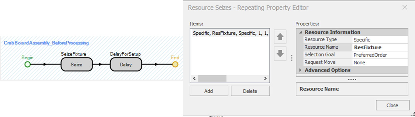
Figure 7.11: Seizing One Unit of Fixture Capacity and Delaying
7.5.4 When the package is finished, the fixture must be removed and released for the next assembly. This process has to be done for each of the three packers, so it will be easier to create a reusable process that is invoked when the board exits the packing stations. From the “Processes” tab, click the “Create Process” button to name the new process RemoveFixture. The Delay step and the Release step are shown in 7.12. The delay will take a Uniform(2,4) minutes to tear down the fixture before the fixture is released.
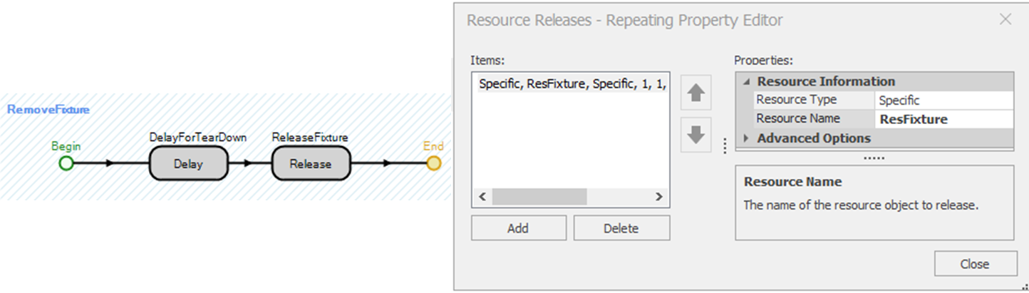
Figure 7.12: Teardown and Release the Fixture
7.6 Tokenized Processes
The previous section showed how the exact same process could be reused in multiple locations. However, if the process was not completely identical (i.e., the teardown time depended on which packer), a process may be given arguments through the tokens that execute them. These processes execute similarly to arguments in a programming language subroutine or subprogram. They parameterize the process or what we call a “tokenized” process since it requires custom tokens.
The need for a tokenized process occurs whenever you have several almost identical processes. For example, the time in system statistics for assemblies as they start to be packed at SrvPacker1 after the first four hours of the simulation was needed. The “solution” was to create a process specialized to computing the time in system to that packer. If we wanted that same time in system for SrvPacker2 and SrvPacker3, we would need to create two new processes, one for each packer and two more statistics. We could probably copy the first packer process for the second two and edit them accordingly. Of course, every time one copies and edits something, there is an increased chance of making an error. Also, if a change or additional behavior is needed later, all three processes would need to be updated.
7.6.1 Let’s instead consider using a Tokenized Process that passes in the particular statistic to record the operation. First, define new time in system (Tally) statistical elements for Packer2 and Packer3 as seen in 7.13, and do not forget to change the Unit Type property to “Time.“

Figure 7.13: Tally Statistics for Packers 2 and 3
7.6.2 Recall a Token is created in order to execute the steps of a process. Therefore, parameters are passed to the process via a custom Token. From the “Definitions→Token” section, add a custom Token named TknPacker. This Token needs an additional “Element Reference” state variables87 named TStaTallyStat, to reference the correct statistic that will be used to store a parameter, as seen in 7.14.

Figure 7.14: TknPacker State Variables
7.6.3 Rename the SrvPacker1_Processing add-on process to SrvPacker_Processing and specify its properties, as seen in 7.15. Change the type of Token that will execute the process steps to TknPacker. Then specify the Input Arguments property with the one row (input arguments) as defined in 7.16, which specifies the input parameter’s name and how it is linked to the customized token.88

Figure 7.15: Properties of the SrvPacker_Processing Process
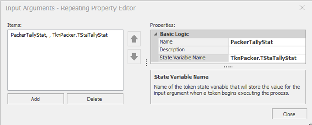
Figure 7.16: Input Arguments for the Process
7.6.4 Next, in **SrvPacker\_Processing, update the Tally step Tally Statistic Name to TknPacker.TStaTallyState** is shown in 7.17.

Figure 7.17: Updated Properties of the Tally Step
7.6.5 Finally, invoke the SrvPacker_Processing at each packer by specifying its individual argument. 7.18 shows the example for Packer 2.
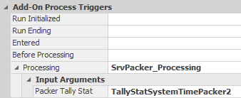
Figure 7.18: Invoke the Tokenized Process
7.7 Commentary
- SIMIO's process capability is one of its standout features. It allows for powerful and unique extension and customization. Using it requires a potential change in thinking about simulation modeling.
- A lot of different modeling can be done with resources, a feature we will explore more in later chapters.
You can have more than one Token associated with the same ModelEntity which will be seen in later chapters.↩︎
When performing more than one assignment, it is recommended you perform all of them in the Assignments (More) to avoid issues of duplication, etc. The single assignment is performed before the Assignments (More).↩︎
In the later chapters on sub-classing we will explore how SIMIO does the assignments when we take apart some of the basic objects.↩︎
Utilize the single assignment for this exercise.↩︎
Recall, Elements are behaviors of objects that can change state over time.↩︎
TimeNow is the current time of the simulation and TimeCreated function returns the time the entity was created.↩︎
When you delete a node, all the connections to it disappear. You can quickly connect nodes by holding the Shift and Ctrl key down, and clicking on the origin node and dragging a connector to the destination. You will need to select the type of connection (here we used TimePaths whose TravelTime is a reference “TimeToExit”.↩︎
Double clicking on the Exited Add-on process trigger property will automatically create the process as well as take you to the “Processes” tab.↩︎
Internally the Separator utilizes an UnBatch step to separate the parent and member entities and then sends them out the appropriate output nodes.↩︎
In this case the second token will cause four tallies – one for each of the four chips. Furthermore, the execution of the “member” occurs before the execution of the “parent” from an Unbatch.↩︎
The members are unbatched into “FreeSpace”, which designates nowhere in particular, but they take up computer memory.↩︎
People often try to avoid using processes at first, especially if they can model without them (this is part of the “different thinking” required in SIMO). However you will find that the time invested in learning to use processes will pay off handsomely as you encounter more complex systems. The remaining chapters will illustrate why processes are so essential.↩︎
Tokens always have the state variable ReturnValue.↩︎
Notice, you can also specify the process return values which might be useful if one process calls another process.↩︎