Simulation Modeling with Simio - 6th Edition
Chapter
18
The Anatomy of Objects: Server
Many simulation languages do not have the ability to modify the behavior of the objects and thus require another object to perform supporting activities (reneging is an example). Unlike most simulation languages, if you do not like the way the designers of SIMIO implemented the Server object (or any other SIMIO object), you can modify it or create your own object.
18.1 A Simple Resource Model: Warehouse Pickup
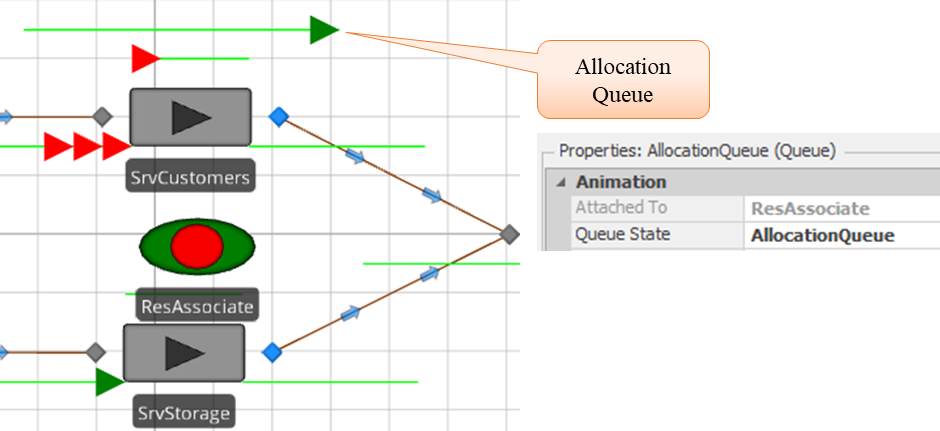
A warehouse store has a pickup area, as illustrated in Figure Figure 18.1 where customers come for items that are not stored on shelves. The pickup area is serviced by an associate who waits on those customers. Because the pickup area does not require the full attention of the associate, the associate is also asked to do some specialty stocking. Quite appropriately, the store wants the customers serviced before doing any stocking.
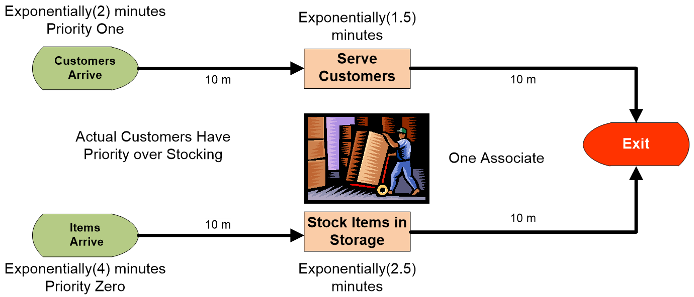
Figure 18.1: Warehouse Operations
18.1.2 Insert two Sources named SrcCustomers and SrcItems and two ModelEntities named EntCustomers and EntItems.
- The SrcCustomers should create EntCustomers, while the SrcItems create EntItems.
- Customers arrive exponentially every two minutes, while items arrive exponentially every four minutes.
- Color the EntCustomers red.
- Set the Initial Priority to zero for EntItems since, by default, ModelEntities have a priority of one.
18.1.3 Insert two Servers named SrvCustomer and SrvStorage and one Sink named SnkExit.
- Each of the Servers should have a capacity of one.
- The Processing Time property for SrvCustomer should be set to Exponential(1.5) minutes and Exponential(2.5) for SrvStorage.
- Connect the two Sources to their appropriate Server via 10-meter logical paths and the two Servers to the Sink via ten-meter paths as seen in Figure 18.2.
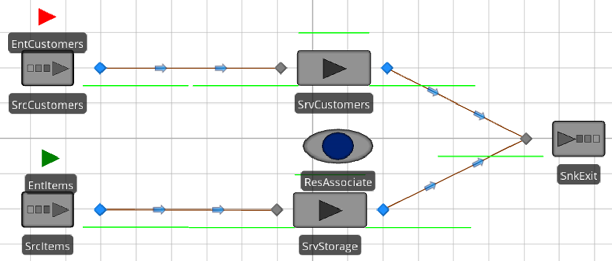
Figure 18.2: Model of a Warehouse Pickup Stations
18.1.4 Insert a fixed Resource named ResAssociate between the two Servers, as seen in Figure 18.2, to constrain the processing of entities.
- Change the ResAssociate’s Dynamic Selection Rule property to be “Largest Value First” with the Value Expression left as the default property (i.e., Candidate.Entity.Priority. This should force the associate to service the customers first if there is a choice.
- Recall the Resource, which has seven defined states defined by the ResourceState variable. In order to visually indicate the type of part that is currently being served, add an additional symbol coloring the round circle red and the outside green for the 8th symbol to represent busy for red parts. Then select the 1st symbol and color the iris green, as seen in Figure 18.3.
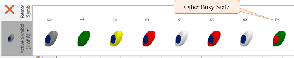
Figure 18.3: Adding an Additional Symbol for Associate
18.1.5 From the Definitions→States section, add a new discrete Integer state variable named GStaAssociatePicture to be used to specify the symbol associated with the customer type since the Resource picture cannot be specified directly.
18.1.6 Change the Current Symbol Index of the property of the ResAssociate to use the new state variable, as seen in Figure 18.4. If the state is busy and the entity is a customer, then display the 7th symbol; otherwise, show the default state symbol.

Figure 18.4: Animation Symbol Index
18.1.7 From the Processes tab, create two new processes named SeizeAssociate and ReleaseAssociate. The ReleaseAssociate process should release the associate while the SeizeAssociate process should seize the associate as well assign the GStaAssociatePicture the value of the ModelEntity.Priority as seen in Figure 18.5.
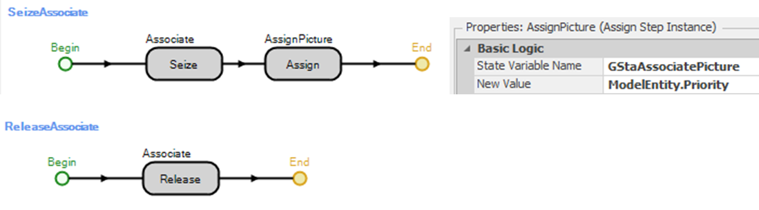
Figure 18.5: Processes for Seizing and Releasing the Associate
18.1.8 For both the SrvCustomer and SrvStorage, specify the Before_Processing add-on process trigger to be the SeizeAssociate process and the After_Processing trigger to be the ReleaseAssociate in a similar fashion.274
18.1.9 Save and run the model.
18.2 Taking an Object Apart to Figure out How it Works
For some reason, a customer waiting at the SrvCustomer does not register a request for service when the associate finishes with another customer. At this point, the problem may not be evident. Unlike other simulation languages, SIMIO objects can be examined by taking them apart and possibly modifying their behavior. Existing objects can be examined as well as modified in SIMIO via “subclassing.”
To try to understand why the queue has not registered the other customers, the Server will be sub-classed to understand its inner workings. Subclassing provides the ability to extend and modify an existing object.
18.2.1 To subclass any of the standard SIMIO objects, right-mouse click on the object in the standard library and choose subclass in the menu option as seen in Figure 18.7.
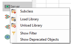
Figure 18.7: Subclassing the Server
18.2.2 After subclassing the Server, select the MyServer object in the [Navigation] panel. Now, all the characteristics of the server are visible. Look at the Definitions→Element’s section. The Server object defines ten different elements: one CostCenter, one Failure, three Stations, one TaskSequence, and four Timer events.
- The CostCenter element is used to define the parent activity-based costing for the object.
- The Failure element is used to define a failure mode. Failure downtime occurrences are started and ended using the Fail and Repair steps.
- The Station element is used to define a capacity-constrained location within an object where one or more visiting entity objects can reside. Each Station defines an EntryQueue and Contents queue. The Contents queue contains the entities that have seized the capacity of the station and are being processed, while the EntryQueue will hold the entities waiting for capacity.
- The TaskSequence element is used to reference the set of tasks that compose the processing time when the Process Type is Task Sequence.
- The Timer element fires a stream of events according to a specified IntervalType (i.e., calendar time, processing count, event count, or processing time). These timers determine when failures occur if a failure has been defined.
When entities arrive at the input node, they are automatically transferred to the “InputBuffer” Station if it has capacity. From the “InputBuffer,” the entities are transferred to the “Processing” station, and once they have finished processing, they will be transferred to the “OutputBuffer” station as seen in Figure 18.8.
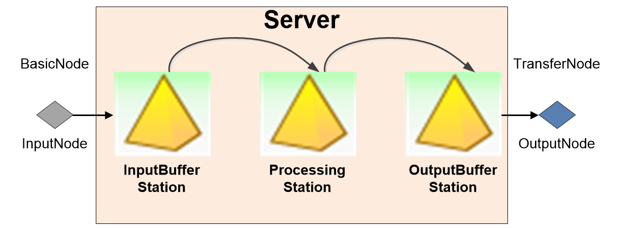
Figure 18.8: Showing the Entity Flow through the Server Object
18.2.3 Next, select the “Processes” tab to look at the behaviors. The Server object defines 13 processes that govern how the Server reacts to failures, capacity changes, entity arrivals and exits, etc. Some of the processes respond directly to events (e.g., entities entering the Processing station, entities entering the Inputbuffer, etc.). The two processes of interest (see Figure 18.9 and Figure 18.10) are the OnEnteredInputBuffer, which is executed when entities enter the InputBuffer station from the input node if the input buffer has capacity, and the OnEnteredProcessing which is executed when entities enter the processing station from either the input buffer or the input node.

Figure 18.9: OnEntered Processes for InputBuffer Station
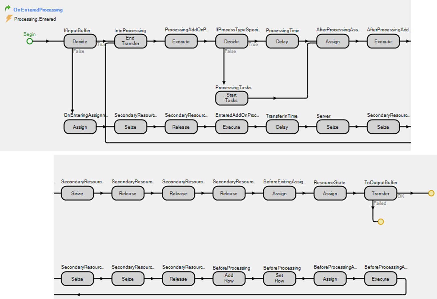
Figure 18.10: OnEntered Processes for Processing Station
When entities arrive at the Server, they are transferred to the InputBuffer, which automatically executes the OnEnteredInputBuffer process which has the following steps. Examination of these steps will yield some insight into our problem.
- Perform any On Entering State Assignments
- Seize and Release On Entering Secondary Resources
- Execute the “Entered” Add-on process trigger. The Execute process step will run the specified process before proceeding.
- Delay for the transfer time if specified.
- End the transfer of the entity into the InputBuffer Station.
- Seize one unit of capacity of the Server.
- Seize and Release processing secondary Resources.
- Once the entity is able to seize capacity of the Server and other secondary resources, it will then execute the “Before_Processing” Add-on process trigger, which in the pickup station model will seize the associate.
- Once it has finished executing the Before_Processing add-on trigger, the entity is transferred to the Processing station, where the other process takes over.
Once entities are transferred to the processing station, the OnEnteredProcessing is invoked, where the actual processing is performed.
- If the input buffer capacity is zero, it goes through the same process as the OnEnteredInputBuffer (i.e., the false branch of the Decide step).
- End the transfer of the entity into the Processing Station.
- Execute the “Processing” Add-on process trigger.
- Depending on “Process Type,” either start processing tasks or Delay the entity based on the processing time specified.
- Once the entity has been delayed or the tasks have finished, it will then execute the “After_Processing” Add-on process trigger, which in the pickup station model releases the associate.
- Seize and release any Secondary Resources.
- The entity will either exit the Server or be transferred to the OutputBuffer station if the capacity of the output is greater than zero.
The first clue to understanding our problem is that the Before_Processing add-on process trigger is not executed until the entity is able to seize the capacity of the Server.
18.2.4 Next, examine the OutputBuffer Entered and Exited processes as seen in Figure 18.11.
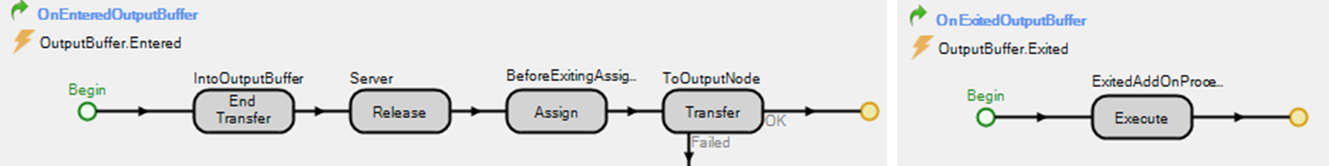
Figure 18.11: OnEntered and OnExited of the Output Buffer Station
The OnEnteredOutputBuffer process will be invoked when the entity is transferred to the OutputBuffer Station and goes through the following steps.
- Ends the transfer into the output buffer station.
- After ending the transfer, the entity releases capacity of the Server at this point.
- It then performs the before-exiting state assignments.
- The entities are then transferred to the output node, which invokes the OnExitedOutputBuffer process, which executes the “Exited” add-on process trigger.
18.2.5 Now, it can be seen that the After_Processing add-on process trigger, which releases the associate, happens before the Server capacity is released. Therefore, the customer waiting in the input buffer cannot request the associate before the associate evaluates the current requests since it first has to seize the server before the SeizeAssociate process is executed.
18.2.6 To fix the problem, set the capacity of the two Servers to “Infinity” which will eliminate the Server constraints. Therefore, every entity entering the two servers will immediately execute the After_Processing add-on process trigger and request the associate.
18.2.8 Setting the capacities to “Infinity” eliminates the problem. However, there are situations where the Server capacity should not be infinite because available space in the server may also limit the number of entities being served. For instance, there may be more than one associate but no room to serve more customers. Notice from Figure 18.11 that the Exited add-on process trigger happens after the Release step and can be used to release the associate.
- Change the capacity of the Servers back to one.
- Remove the After_Processing add-on process trigger from each Sever by setting the value to null, removing it manually, or right-clicking and then selecting Reset.
- Choose the ReleaseAssociate as the Exited add-on process trigger for both Servers.
18.2.9 Save and run the new model. You may want to increase the item arrival rate to one or two per minute.
18.2.9.1 After observing the model for a while, does the associate always service customers first?
_______________________________________________
In other instances, having the correct order may have resulted in the same phenomena owing to zero time events, which can be checked by looking at the “Model Trace.” Recall one can reorder the zero time events by placing a Delay step right before a step you want to force to the end of the zero time by delaying it for zero time using Math.Epsilon, as seen in Figure 18.12. When SIMIO encounters a delay of Math.Epsilon, it places the steps after at the end of the current event time.
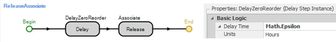
Figure 18.12: Adding the Zero Time Delay
18.3 SIMIO Objects and Class Hierarchy
Objects are created (instantiated) from classes. The act of clicking on a SIMIO object in the [Standard Library] panel and dropping it into a position on the modeling canvas causes an object or model of that type to be created (instantiated). The object will possess all the characteristics defined for that class. Once on the modeling canvas, you can change (even delete) its “Default” characteristics, such as initial property values, processing time, capacity, add-on processes, and so forth. You can also add your own properties, events, states, and elements. Each SIMIO object will have its own collection of processes, elements, properties, states, and events. Objects can be saved in a library and used in other objects. SIMIO makes no distinction between a model and an object.
Figure 18.13 shows the base object classes in SIMIO as well as the [Standard Library] model classes. New classes can be created from base classes, and new classes can be obtained from the [Standard Library] (or your library) by “sub-classing”.
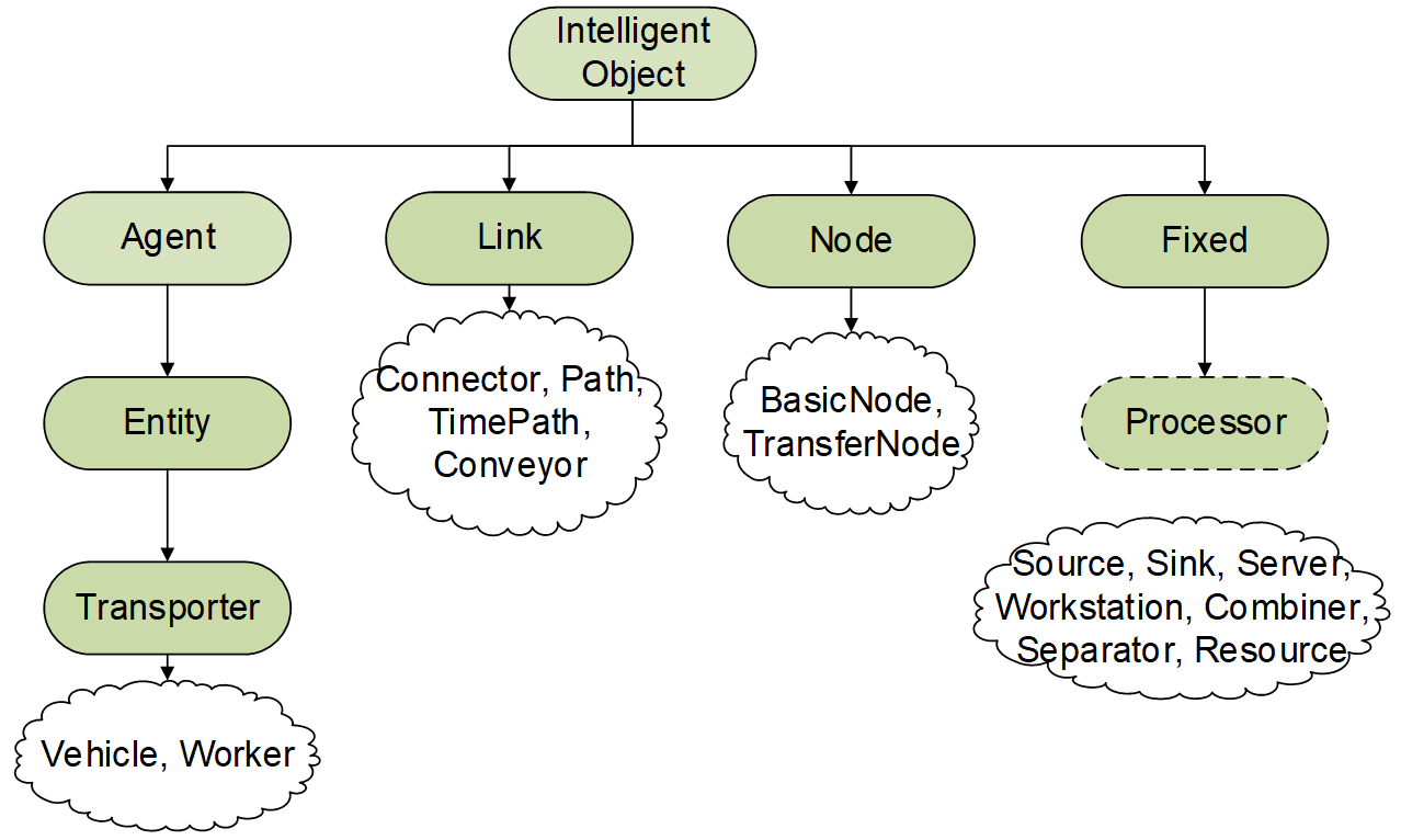
Figure 18.13: SIMIO Class Hierarchy
The “origin” object class is the Intelligent Object (IO) class, which allows objects to be seized and released and respond to schedules. The Agent class inherits the properties and characteristics of the IO class but adds additional characteristics and behaviors (i.e., objects that can be dynamically created and destroyed as well as move around in continuous and discrete space (grid)). The Link adds the ability (i.e., properties and behaviors) for Entities to enter, exit and move along. Entities are specialized agents that have the ability to move on links (paths, conveyors, and connectors) as well as move in and out of Fixed objects (combiners, servers, workstations). Fixed objects represent intelligent objects that are fixed and don’t move in the space. The Transporter is a more specialized entity that has the additional capability of being able to pick up and drop off entities. They can do this by moving in free space or along links. Currently, models cannot be created directly from the Intelligent Object or from the Entity classes.
New object classes in SIMIO may be defined by extending or modifying the current SIMIO objects. In object-oriented terms, this method of extension is referred to as specialization or “subclassing.” When a model is subclassed, it inherits all of the characteristics (i.e., processes, elements, properties, states, and events) but has the capability to modify those inheritable features as well as add new ones.
The SIMIO [Standard Library] object classes should be viewed as model classes that have been specialized from other classes. Some of their characteristics are derived from the base classes, but some characteristics are added or changed. For example, a worker object is a specialization of an entity that can act as a Resource and a Vehicle. Workers and Vehicles are specialized Transporters. Several properties (e.g., Initial Node, Idle Condition, etc.) can be modified and added as well as adding new process logic to force the entity to behave similar to resources and vehicles. The Link, Node and Server objects have the same properties as the Fixed class but add more functionality. Likewise, the Path, Connector, and Conveyor objects are more specialized versions of the Link class. The Server class is a fairly general object used to constrain and delay entities in the system. The Processor class is a specialization of the Fixed class.
Extending and adding objects is an important feature of SIMIO that needs to be studied carefully. Thus, if you are only going to need the sewing machine class for one instance of one model, you may not want to take the time to create an object class. However, if you’re going to use this class in multiple places, then having a reusable object will be important and its utility will be demonstrated over the next few chapters.
SIMIO uses a three-tier object hierarchy composed of the “object definition,” the “object instance,” and the “object realization.” The object definition is simply the specification of the object class through its processes, states, elements, properties, and events. The definition may be determined by the SIMIO developers for the base classes and [Standard Library] objects. However, a modeler may create their own object definitions (as seen in the next chapters). The object definition is shared by all instances from that class. While all objects from the same class share the same definition, each object instance has its own characteristics, such as its own add-on process, state variable value, capacity, etc. The object instance may have its characteristics changed during the simulation.
Object realizations hold the state values for the instances, and these occupy a fixed location in the model. However, Entities, Vehicles, and Workers are dynamic and are created from the instance definition during the execution of the simulation. So SIMIO creates static representation for that part of these object definitions that are common, but then creates a dynamic representation for the instances that move throughout the simulation. You can see this in the model with a vehicle, whose object realization shows on the modeling canvas, while the individual vehicles move around the model.
You can select both of them at the same time and specify the add-on process triggers.↩︎